Injection Molding Machine Chapter 4
V3.0
4-20
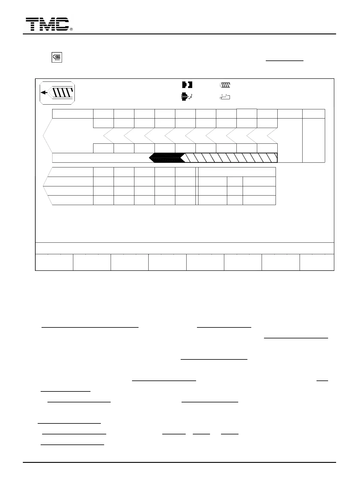
2.9 Injection setting
Press hot key or use the direction key to move the cursor to the INJECTION
,
press
ENTER to display this screen.
10h25m10s
20°C
CUSHION MONITOR:LOW
30
40
PARAMETER
INJ. MONITOR T.
0.50
03D05M07Y
INJ.
F2F1
MENU
04
INJ. DELAY T.
COOLING T.
5
HOLD P.
V %
TIMEsec
P bar
40
10
PT mm
P bar
10.0
INJ.V
V %
9
3W
< 8.0>
INJ. PRESS ACTUAL
000
,HIGH
< 9.0>
INJ. SPEED ACTUAL
INJ. START PT.
INJ. END PT
MOLD
SUPPORT
F3 F4
AUTO INJ.
PURGE PROFILE
< 0.0> 000.0
< 4.0> 000.0
F5 F6
CHANGE
LOG
PROD.
MANAG.
F7 F8
FUNCTION
000.0
000
000.0
100.0mm
100.0mm
10
P/V TRANS. POINT
< 10.0>
<1.0>
< 000>
140
50.0
432
10
60
0.50
50
0.50
10
70
0.50
10
100.0sec
140
20.0 30.0
40.0
140 140
1
PT mm
TIME
P bar
140
10
0.50
OFF
OFF
ON
70.0
140
60.0
140
140
80.0
78
50 60 70
6
1.0mm
9080
54
100
32
110.0mm
9.9
0.6
000
105.0
100.0
140
+10.0
0/ 0
0/ 0
SUCK.B
0/ 0
CH.END
1
15
P1: P2:
0/ 0V1: V2:
ACTION STATUS
M.:
Screen 4-12
2.9.1 Three major stage of injection V / P
V Injection speed control
1. INJ. SPEED < > SECTION
can be set on the INJECTION PAR. screen.
2. It is recommended to set low speed to 10~20%. 3.0~10.0 mm before P/V TRANS. POINT
position.
3. It is recommended that the pressure before P/V TRANS. POINT should be the reading of
actual maximum injection pressure plus 10 bars.
4. All pumps are active before P/V TRANS. POINT while only small pump is active after P/V
TRANS. POINT thus reduces energy consumption.
5. If P/V TRANS. POINT is not reached before INJ. MONITOR T. times up
,
alarm is fired.
/ P/V TRANS. POINT
1. P/V TRANS. POINT
: One or more of PT mm
,
TIME
or P bar must be selected to control
P/V TRANS. POINT
,
any one condition is made
,
injection filling process will be switched to
holding process.
 Loading...