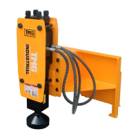
This document is a product manual for the TMG Industrial Skid Steer Hydraulic Post Driver, Model TMG-PD700S. It provides comprehensive information regarding the device's function, technical specifications, usage, and maintenance.
Function Description:
The TMG Industrial Skid Steer Hydraulic Post Driver is designed for driving posts into the ground using hydraulic power from a skid steer. It operates by delivering impacts to a specialized tool, which in turn drives the post. The internal mechanism involves a piston that is reciprocated by hydraulic pressure, and a cushion chamber charged with nitrogen (N2) gas that compresses during upward strokes, storing energy for the next blow. The front head supports the post driver hammer, and the upper bushing prevents shock from the tool. The driver chisel/tool transfers impact power to the objects (posts).
Important Technical Specifications (Model FD700S):
- Operating Weight: 398 kg
- Working Flow Rate: 36-60 liters/min
- Oil Relief Pressure: 170 kg/cm²
- Working Pressure: 110-140 kg/cm²
- Impact Rate: 500-900 bpm (blows per minute)
- Chisel Diameter: Ø68 mm
- Hose Diameter: 1/2 inch
- Back Head Pressure: 16 kg/cm²
These specifications are subject to change without prior notice for quality improvements.
Usage Features:
The manual outlines a detailed operation method and precautions for using the post driver.
- Preparation: Before operation, a pilot hole may be drilled in rocky or frozen soil. The driver is then positioned over the desired location, and the pile is secured. The driver is lowered until its weight is supported by the pile, and the loader arms are lowered.
- Operation: The driver presses the pile to drive it into the ground. Operators are warned not to allow the post driver hammer to fall onto the pile, as this can cause excessive force and damage to the hammer and base machine.
- Safety Precautions:
- Thorough training and supervision are required.
- Familiarization with carrier controls is essential, operating at a slow pace initially.
- All controls must be in neutral before starting the carrier.
- The boom should always be lowered, and the parking brake engaged before leaving the carrier.
- The engine must be stopped before any repairs or adjustments.
- Operation is not recommended at oil temperatures above 175°F/80°C to prevent damage and reduced performance.
- Do not operate a damaged, leaking, improperly adjusted, or incompletely assembled post driver hammer.
- Modifications to the hammer are prohibited.
- Only authorized and trained personnel should perform repairs and maintenance.
- Operators must not be under the influence of medication, drugs, or alcohol.
- The post driver hammer should be removed from the carrier during transport.
- Excessive vibration of hoses indicates a need for immediate disassembly and repair.
- Continuous blank hammering or operating with the tool not fully engaged can damage the base machine and the tool.
- The engine of the base machine should be warmed up for 5-10 minutes, especially in winter, before operation.
- Do not touch the tool during operation due to high temperatures.
- Ear, eye, and breathing protection are mandatory during operation.
- Greasing the driver tool cavity through the nipple with down pressure is important.
- Eye protection must be worn when removing the stop pin.
- Tool Replacement: The manual provides instructions for removing and installing the stop pin and tool. It emphasizes checking for wear, breakage, and scores, and lubricating the tool pin and movable areas. The tool shank should be well lubricated before installation. The standard inner diameter of the bottom portion of the driver chisel is 200mm. The tool bush should be replaced if the gap between the tool and the tool bush exceeds 4mm, as this can lead to the piston failing to hit the tool correctly.
Maintenance Features:
Regular maintenance is crucial for optimal performance and longevity.
- Daily Inspection: Before operation, inspect for loose, missing, or damaged bolts and nuts, visible damage to hoses and oil leakage, abnormal oil leakage, abnormal wear or cracks on the tool, proper greasing (5-10 pumps every 2-3 hours), level and contamination of hydraulic oil, missing rubber plugs, and snap rings.
- Periodic Maintenance (Every 100 hours):
- Remove the tool and all grease from the bushing. Avoid pressure washers, steam, or solvents.
- Check for chips or cracks inside the housing and on bushing surfaces, which can indicate insufficient lubrication, inappropriate grease, or improper operation (blank hammering, side loading).
- Check wear on the tool pin (shoulders and side surface) and rotate or replace if worn or deformed.
- Check wear on the chisel holder bushing. Replace the tool, bushing, or both if combined wear exceeds 5mm. Replace bushings when grooves are worn through.
- Replace damaged or worn parts.
- Clean all components and hand grease the tool shank and chuck bushings before reassembly.
- Regular Inspection & Maintenance: Essential for best condition. Consult a service station for regular inspection and maintenance, and contact the local dealer for inspection within six months after delivery.
- Nitrogen (N2) Gas Inspection and Charging:
- The N2 gas pressure in the back-head changes according to tool condition.
- Lay down the breaker and fully extend the tool.
- Stay clear of the tool during charging, as it may be impacted by the piston.
- N2 gas must be discharged when through bolts are changed.
- Only nitrogen gas should be used.
- A conversion table for charging N2 gas pressure to the back head is provided, correlating gas pressure (Bar) with surrounding temperature (°C).
- The manual details the procedure for connecting the N2-gas charging tools and charging the back-head, including steps for checking pressure and releasing excess gas.
- Troubleshooting Guide: A comprehensive guide is provided for common issues such as "No blow out," "Low impact power," "Irregular impact," "Bad tool movement," "Oil leakage between front head and tool," and "Gas leakage." For each symptom, potential causes and required actions (e.g., re-adjusting gas pressure, filling hydraulic oil, replacing seals, contacting service shops) are listed.
- Oil Leakage: The manual includes a diagram and table detailing areas of oil leakage, conditions, and causes/remedies (e.g., seals cammed, loose hoses, oil leaking from reassembly, damaged o-rings).
The manual emphasizes the importance of safety, proper operation, and regular maintenance to ensure the efficient and safe use of the TMG-PD700S Skid Steer Hydraulic Post Driver.