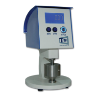
The TMI Digital Micrometer 49-8X Series is a precision thickness measuring instrument designed for sheet materials. It combines a dead weight micrometer principle with a digital readout, ensuring high precision and eliminating operator influence. The device is manufactured by Testing Machines Inc., a leader in physical testing equipment for over 80 years.
Function Description
The micrometer measures the thickness or caliper of various sheet materials, including paper, natural or synthetic fabrics, leathers, metals, plastics, and rubber. The motor-driven instrument automatically displays the specimen thickness on a digital readout. The lower anvil and movable pressure foot are made from lapped, stainless steel, ensuring accurate and consistent measurements. Models 49-86 and 49-87 include an on-board statistics package that stores up to 100 readings, calculating and displaying the average, standard deviation, maximum, and minimum values.
Important Technical Specifications
- Dimensions: 7 in. (15cm) wide x 12 in. (30.5cm) high x 9.5 in. (24cm) deep
- Approximate Weight: 22 lb. (10kg)
- Power Requirements: 90-264VAC, 50/60 Hz
- Measurement Ranges:
- Models 49-85 and 49-86:
- Imperial Units: 0-0.050 in. x 0.0000254 in. resolution
- SI Units: 0-1.270mm x 0.0005mm resolution
- Model 49-87:
- Imperial Units: 0-0.50 in. x 0.0000254 in. resolution
- SI Units: 0-12.70mm x 0.0005mm resolution
- Serial Communication Parameters (via Mini USB connector):
- Baud: 9600 bps
- Data Bits: 8
- Parity: None
- Stop Bits: 1
- Flow Control: None
- Fuse: 0.25 Amps (TMI # 680-075)
Usage Features
- Digital Readout: The display window shows the measured thickness.
- Cycle Button: A blue illuminated push button switch on the front right side controls the movement of the anvil spindle and pressure foot.
- Zero Button: Used to zero the machine when it rests on the lower platen or another static object. In menus, it navigates highlighted options.
- Units Button: Located in the middle of the front panel. For the 49-85, it cycles through units (µm, mils, millimeters, inches). For 49-86 and 49-87, it accesses and navigates statistics pages and menus.
- Split Weight: TMI # 49-76-00-15 (Standard Model) contributes to the dead weight.
- Lower Anvil: An optically flat testing surface where the specimen is placed.
- Pressure Foot: Moves up and down to perform measurements.
- Anvil Spindle: Carries the weight and pressure foot.
- On/Off Switch: Located on the back of the unit, integrated into the power entry module.
- Serial Output: RS-232 output via a Mini USB connector for data collection.
- Setup Procedure:
- Place the micrometer on a rigid, level bench top, free from temperature variations, air currents, and vibration.
- Crucially, remove the shipping collar from the anvil spindle. Failure to do so can cause serious damage.
- If included, mount the Split Weight using a 9/64" Allen Wrench. Handle split weights with care due to sharp edges.
- Remove the rubber pad between the anvils (for 0.000"-0.050" range, gently lift the upper anvil).
- Connect the power cord to a suitable AC outlet, free from electrical noise. Ensure the power plug is adapted by a qualified electrical engineer if necessary, and equipped with a safety earth terminal.
- Turn the power switch to "On." The display and start/stop button will illuminate.
- The machine will cycle 2-3 times to find its travel limits; press the Units button to initiate this. The blue LED button will pulse during cycling.
- Clean the anvils by drawing a piece of soft-body paper through the pressure foot and anvil. Inspect for debris and use rubbing alcohol if needed.
- Allow the micrometer to warm up for at least 30 minutes before testing.
- Zero the Micrometer by pressing the Zero button.
- To measure, place the specimen between the automatically cycling pressure foot and anvil when they are apart, ensuring it fully covers the contact area. The thickness is displayed when the pressure foot rests on the specimen.
- User Options Menu (49-86 and 49-87 only): Accessed by pressing and holding the Units Button and then pressing the Zero Button from the main screen.
- Password Protection: Optional 4-digit code to protect the menu. Default is 0-0-0-0 (disabled).
- Lowering Speed: Options include 1, 2, and 5mm/s (10mm/s for 49-87 only), as specified by standards.
- Dwell Time: Options for 0-6 seconds, specifying the pause after spindle motion stops before reporting a result.
- Starting Units: Sets the default units (µm, mils, mm, inches) on power-up.
- Record Stats: ON/OFF setting for recording new readings for statistics.
- Stat Threshold: Sets a tolerance band (OFF, 2 µm, 4 µm, 6 µm) around zero; readings within this band are not recorded for statistics.
- Zero Threshold: Sets a small range (OFF, 2 µm, 4 µm, 6 µm) around 0.00 to be reported as 0.00.
- Time: Options for 24Hr/A.M./P.M., adjusting hours, minutes, and resetting seconds.
- Live Readings: ON/OFF setting for constant display of the updated gap on the main screen.
- LED Pulse: Toggles the Cycle Button's LED between constantly on and pulsing during a test.
- Statistics (49-86 and 49-87 only):
- Access from the main screen by pressing the UNITS button.
- Displays current reading, average, standard deviation, maximum, and minimum.
- Press UNITS again to list readings. Navigate with ZERO key (↑, ↓, DELETE, RETURN).
- Press and hold UNITS, then ZERO to delete all readings (user confirmation required).
- Press and hold UNITS, then ZERO to return to the main screen.
Maintenance Features
- No Oiling or Special Maintenance Required: The TMI Digital Micrometers – 49-8X Series are designed for minimal maintenance. A rise in operating temperature to reach operating temperature is normal.
- Cleanliness: Keep the instrument clean and in a dirt/dust-free environment. Regularly clean the anvil and pressure foot for consistent readings.
- Storage: If not in use for an extended period, use a plastic cover to protect it from dirt. Place a piece of paper or film between the pressure foot and anvil to prevent prolonged contact.
- Calibration: The machine is factory-calibrated. Due to its technical nature, calibration should ideally be performed by factory-trained personnel.
- Use TMI gauge blocks (35-12-02 for 49-85/86; 35-12-03 for 49-87) for calibration checks.
- Ensure gauge blocks are clean with alcohol and handled without touching working surfaces.
- Parallelism Check/Adjustment:
- Always check anvil parallelism first using a .010 in. gauge block on the right, left, front, back, and center of the anvils.
- For 49-85 and 49-86, readings must be within 0.00004 in. of each other.
- For 49-87, readings must be within 0.0002 in. of each other.
- If readings are outside tolerance, adjust the three leveling screws underneath the base plate using an Allen key and a 3/8 in. wrench. This adjustment should only be made by a trained professional.
- For 49-86-00-0003 and 49-87-00-0003, perform three sets of readings and adjust screws iteratively to establish baseline parallelism. Only adjust if measurements with gauge blocks at the visual center of the anvil are outside calibration record tolerances.