6
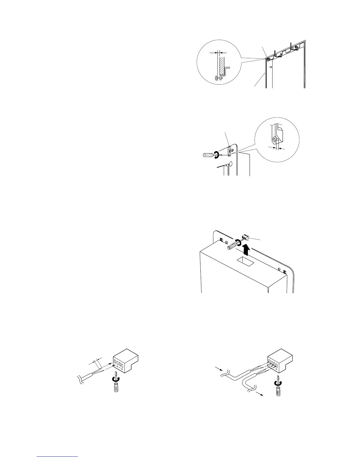
Step 5. Install the supplied speaker fixing screws (4
pieces with M4x30 plain and spring washers) in
the mounting bracket so that they are left
sticking out 2 – 3 mm from the mounting
surface. (They are tightened in Step 10.)
Step 6. Loosen the unit's lock tab screws (4 places) and
leave them sticking out 2 – 3 mm. (They are
tightened in Step 10.)
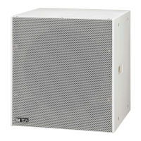
Step 7. Connect the speaker cable to the detachable connector.
Note: Solid or stranded cables with a cross-sectional area of 0.2 – 2.5 mm
2
(corresponding to AWG24 – 14)
can be used.
Step 7-1. Detach the input connector from the unit's
connector socket and loosen the screws of
the terminals to use with a screwdriver.
Step 7-2. Insert stripped cable ends into the terminals, then retighten the terminal screws.
Note: Tighten the screws of the unused terminals to
prevent resonance noise.