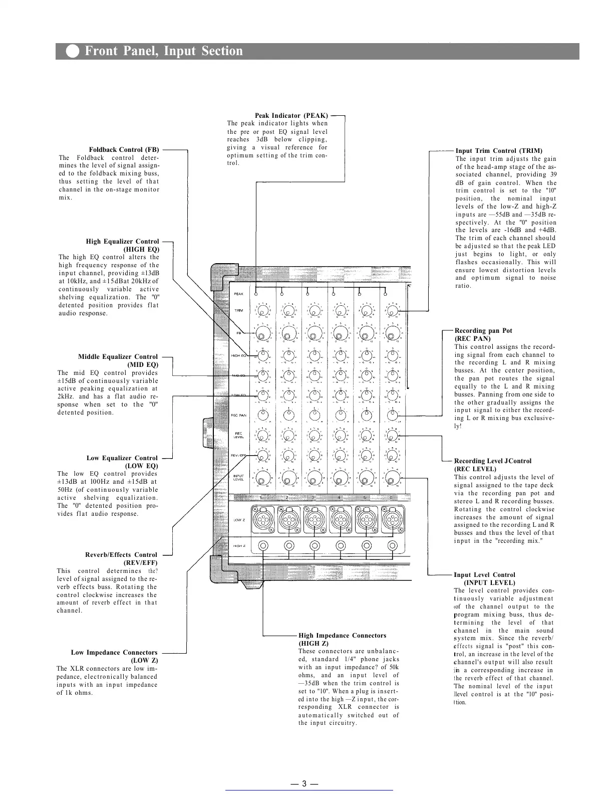
Foldback Control (FB)
The Foldback control deter-
mines the level of signal assign-
ed to the foldback mixing buss,
thus setting the level of that
channel in the on-stage monitor
mix.
High Equalizer Control
(HIGH EQ)
The high EQ control alters the
high frequency response of the
input channel, providing ±13dB
at 10kHz, and ±15dBat 20kHz of
continuously variable active
shelving equalization. The "0"
detented position provides flat
audio response.
Middle Equalizer Control
(MID
EQ)
The mid EQ control provides
±15dB of continuously variable
active peaking equalization at
2kHz. and has a flat audio re-
sponse when set to the "0"
detented position.
Low Equalizer Control
(LOW
EQ)
The low EQ control provides
±13dB at l00Hz and ±15dB at
50Hz (of continuously variable
active shelving equalization.
The "0" detented position pro-
vides flat audio response.
Reverb/Effects Control
(REV/EFF)
This
control
determines
the?
level of signal assigned to the re-
verb effects buss. Rotating the
control clockwise increases the
amount of reverb effect in that
channel.
Low Impedance Connectors
(LOW
Z)
The XLR connectors are low im-
pedance, electronically balanced
inputs with an input impedance
of 1k ohms.
Peak Indicator (PEAK)
The peak indicator lights when
the pre or post EQ signal level
reaches 3dB below clipping,
giving a visual reference for
optimum setting of the trim con-
trol.
High Impedance Connectors
(HIGH Z)
These connectors are unbalanc-
ed, standard 1/4" phone jacks
with an input impedance? of 50k
ohms, and an input level of
—35dB when the trim control is
set to "10". When a plug is insert-
ed into the high —Z input, the cor-
responding XLR connector is
automatically switched out of
the input circuitry.
Input Trim Control (TRIM)
The input trim adjusts the gain
of the head-amp stage of the as-
sociated channel, providing 39
dB of gain control. When the
trim control is set to the "10"
position, the nominal input
levels of the low-Z and high-Z
inputs are — 55dB and —35dB re-
spectively. At the "0" position
the levels are -16dB and +4dB.
The trim of each channel should
be adjusted so that the peak LED
j u s t begins to l i g h t , or onl y
flashes occasionally. This will
ensure lowest distortion levels
and optimum signal to noise
ratio.
Recording pan Pot
(REC
PAN)
This control assigns the record-
ing signal from each channel to
the recording L and R mixing
busses. At the center position,
the pan pot routes the signal
equally to the L and R mixing
busses. Panning from one side to
the other gradually assigns the
input signal to either the record-
ing L or R mixing bus exclusive-
ly!
Recording Level J Control
(REC LEVEL)
This control adjusts the level of
signal assigned to the tape deck
via the recording pan pot and
stereo L and R recording busses.
Rotating the control clockwise
increases the amount of signal
assigned to the recording L and R
busses and thus the level of that
input in the "recording mix."
Input Level Control
(INPUT LEVEL)
The level control provides con-
tinuously variable adjustment
of the channel output to the
program mixing buss, thus de-
termining the level of that
channel in the main sound
system mix. Since the reverb/
effects
signal
is
"post"
this
con-
trol, an increase in the level of the
channel's output will also result
in a corresponding increase in
he reverb effect of that channel.
The nominal level of the input
level control is at the "10" posi-
tion.
— 3 —
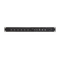
Front Panel, Input Section
Get other manuals https://www.bkmanuals.com
 Loading...