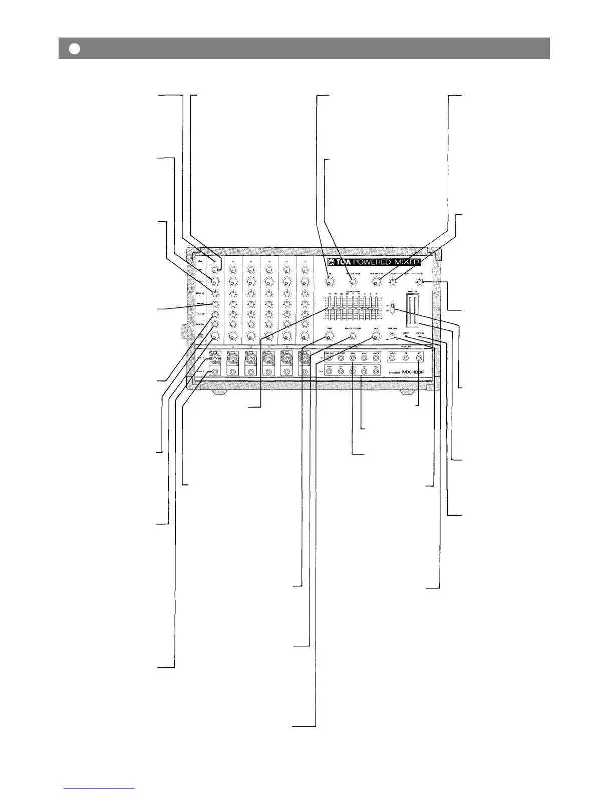
Peak Indicator (PEAK)
The peak indicator lights when
the pre or post EQ signal level
reaches 3dB below clipping,
giving a visual reference for
optimum setting of the trim con-
trol.
Foldback Control (FB)
The Foldback control deter-
mines the level of signal assign-
ed to the foldback mixing buss,
thus setting the level of that
channel in the on-stage monitor
mix.
High Equalizer Control
(HIGH EQ)
The high EQ control alters the
high frequency response of the
input channel, providing ±13dB
at 10kHz, and ±15dB at 20kHz of
continuously variable active
shelving equalization. The "0"
detented position provides flat
audio response.
Middle Equalizer Control
(MID
EQ)
The mid EQ control provides
±15dB of continuously variable
active peaking equalization at
2kHz. and has a flat audio re-
sponse when set to the "0"
detented position.
Low Equalizer Control
(LOW
EQ)
The low EQ control provides
±13dB at 100Hz and ±15dB at
50Hz of continuously variable
active shelving equalization.
The "0" detented position pro-
vides flat audio response.
Reverb/Effects Control
(REV/EFF)
This control determines the
level of signal assigned to the re-
verb effects buss. Rotating the
control clockwise increases the
amount of reverb effect in that
channel.
Input Level Control
(INPUT LEVEL)
The level control provides con-
tinuously variable adjustment
of the channel output to the
program mixing buss, thus deter-
mining the level of that channel
in the main sound system mix.
Since the reverb/effects signal is
"post" this control, an increase
in the level of the channel's out-
put will also result in a cor-
responding increase in the re-
verb effect of that channel. The
nominal level of the input level
control is at the "10" position.
Low Impedance Connectors
(LOW
Z)
The XLR connectors are low im-
pedance, electronically balanced
inputs with an input impedance
of 1k ohms.
Input Trim Control (TRIM)
The input trim adjusts the gain
of the head-amp stage of the as-
sociated channel, providing
39dB of gain control. When the
trim control is set to the "10"
position, the nominal input
levels of the low-Z and high-Z
inputs are –55dB and –35dB re-
spectively. At the "0" position
the levels are –16dB and +4dB.
The trim of each channel should
be adjusted so that the peak LED
just begins to light, or only
flashes occasionally. This will
ensure lowest distortion levels
and optimum signal to noise
ratio.
Foldback Master Control (FB)
The FB master control adjusts
the overall combined signal
level of the six independent
channel foldback sends, and
thus the level of the entire on-
stage monitor mix.
Reverb/Effects to Foldback
Control (REV/EFF TO FB)
This control adjusts the amount
of reverb/effects signal that is
returned to the foldback buss
and thus the level of reverb/
effects contained in the on-stage
monitor mix.
Graphic Equalizer
(EQUALIZATION)
The graphic equalizer is 1/1
octave with 9 independent ac-
tive bands (filters), providing
12dB of boost or cut at each
center frequency. The "0" de-
tented position provides flat
audio response.
High Impedance Connectors
(HIGH Z)
These connectors are unbal-
anced, standard 1/4" phone
jacks with an input impedance
of 50k ohms, and an input level
of –35dB when the trim control
is set t o "10". Whe n a plug is in-
serted into the high –Z input, the
corresponding XLR connector is
automatically switched out of
the input circuitry.
Program Master Control
(PGM)
The PGM control adjusts the
overall combined signal level of
the six independent channel
level controls, and thus the level
of the main sound system.
Reverb/Effects to Program
Control
(REV/EFF TO PGM)
This control adjusts the amount
of reverb/effects signal that is
returned to the program buss
and thus the level of reverb/
effects contained in the main
sound system.
Aux Level Control (AUX)
This control sets the overall
level of the Aux input signal.
Buss Link Jack
(BUSS LINK)
Patching Jack
(PATCH BAY/IN)
Patching Jack
(PATCH BAY/OUT)
Aux Panpot (AUX PAN)
This control assigns the aux-
iliary input signal (a tapedeck,
etc., connected to the aux input
jacks) to either the program or
the foldback mixing busses. At
the center position, the signal is
routed equally to both busses.
Panning from one side to the
other gradually assigns the
signal to either independently.
Power Amp Compression
Indicator (COMP)
The Comp LED lights when the
internal compressor is acti-
vated. The compressor is pro-
vided to protect speaker systems
by compressing the input signal
level of the power amplifier
when clipping occurs in the out-
put stage. Frequent flashing of
the LED is not reason for alarm.
However, a constant or steady
light indicates that the MX-106R
is being overdriven and that the
internal power amplifier is
possibily "under powered" for
that application. The output
level of the MX-106R should be
decreased until the LED only
flashes intermittently.
Reverb/Effects Send Control
(REV/EFF SEND)
This control adjusts the overall
signal level of the effects mix
that is delivered to the internal
reverberation unit, or to an
external effects device through
the effects output. The send con-
trol works in conjunction with
the REV/EFF to PGM and the
REV/EFF to FB controls to set
the overall level of reverb/
effects in the main and monitor
sound systems.
Reverberation Low Equalizer
Control
(REV
LOW EQ)
The low EQ control alters the
low frequency response of the
reverberation signal. The "0" de-
tented position provides flat
audio response.
Reverberation High Equalizer
Control
(REV HIGH EQ)
The high EQ control alters the
high frequency response of the
reverberation signal. The "0" de-
tented position provides flat
audio response.
Graphic Equalizer In/Out
Switch (IN/OUT)
The in/out switch enables com-
parison between a flat response
(out) and the equalized response
(in). The "out" position com-
pletely removes the equalizer
from the MX-106R circuitry.
Fluorescent Bargraph Peak
Meters (PGM/FB)
The high intensity meters enable
visual monitoring of the pro-
gram and foldback output signal
levels.
Power Amp Protection
Indicator (PROTECT)
The indicator LED lights if the
power amplifier output is short-
ed, if the temperature of the unit
rises above acceptable levels, or
if DC is drifted to the speaker
outputs. If the LED should light,
speaker wiring and ambient
temperature of the MX-106R
should be checked. If the LED
remains lighted, the unit should
be referred to qualified service
personnel for repair.
Note:
The MX-106R protection cir-
cuitry will (1) detect 'faulty con-
ditions' within the power amp-
lifier, (2) give a visual indica-
tion, and (3) automatically shut
down until the fault condition is
alleviated. This special circuitry
ensures maximum reliability
and virtually eliminates equip-
ment damage due to unsafe or
fault conditions. Please refer to
fault protection table on page 7
for full explanation of this
important feature.
—
3 —
Front Panel
 Loading...