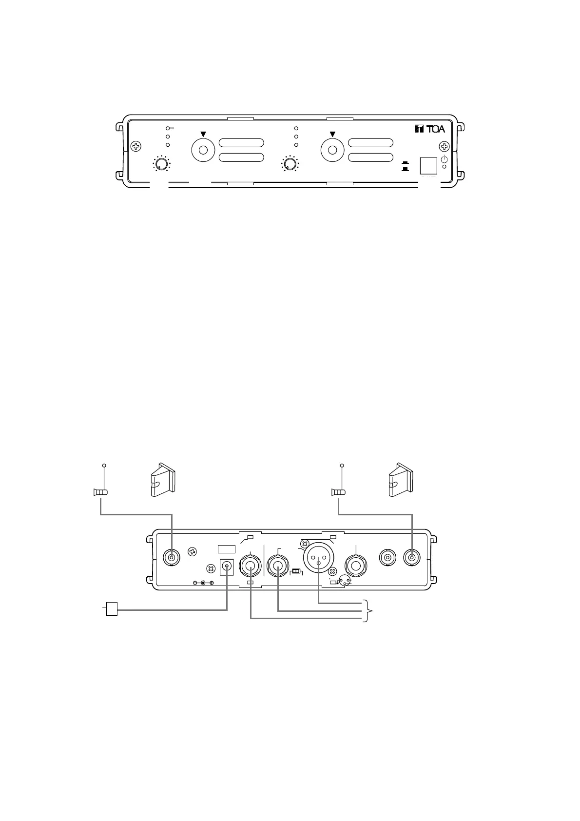
OUT ININ
DC IN OUTPUT MIX IN
MIX/12
ANT AANT B
-20dBV/600Ω(+6dBV Max)
12-18V
250mA(max)
-20dBV/10kΩ
(BALANCED)
SELECTOR
MIX 1
(UNBALANCED)
HOT
COLD
12
3
or
Wall-mounted wireless antenna
YW-4500 (optional)
Accessory
antenna
Accessory
antenna
AC-DC adapter
or
Wall-mounted wireless antenna
YW-4500 (optional)
WT-4820
To the line input of a mixer
or other equipment
[Connection Example 1]
9. CONNECTION
6
8. OPERATION
The following operation procedure is an example for the tuner module 1. The same procedure applies to the
tuner module 2.
010 010
ANT A
ANT B
PEAK
VOLUME
CHANNEL
TUNER
1
ANT A
ANT B
PEAK
VOLUME
CHANNEL
TUNER
2
ON
OFF
POWER
DIVERSITY WIRELESS TUNER WT-4820
1
2
4
Step 1. Turn the unit's power on.
Step 2. Set the channel selector switch to the predetermined channel number using the screwdriver supplied
with the WTU-4800.
Step 3. Turn the wireless microphone's power on.
Step 4. Adjust the wireless microphone volume control for proper level.