NOTICE/WARNING BEFORE OPERATION USE
ACCESSORY & CONFIGURATION
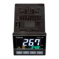
TTM-i4N SERIES USER'S MANUAL
: Cautions,Danger,Refer to a manual
: Alternating current
: Reinforced/dual insulation
: Cautions,Danger of Electric Shock
The meaning of the symbols indicated on the label found at the side of the unit is as follows.
CAUTION
WARNING
Due to mishandling,the serious damages may occur to the operator,such as death,
electrocution or skin burn.
Owing to mishandling,the operator may be inflicted with slight injury,or may cause some
damage to the unit.
1
) Please be sure that the unit enclosed in packing carton is a right model before using.
2
) Kindly check the following accessory being contained in that carton box.
3
) Model Configuration
Thank you for purchasing model TTM-i4N SERIES Digital Temperature Controller.
Please go through this Instruction Manual carefully and use the unit in proper manner.
If the unit is used in a manner not specified by the manufacturer,the protection provided the unit may be impaired.
TTM-i4N- -A
OUT
1
Option
Code
OUT
1
R
Relay Contact Output
P
SSR Driving Voltage Output
Option
B
OUT2/EV2
Relay Contact Output
SPECIFICATIONS
※
Clean the unit by well squeezed cloth with water.
OUTER DIMENSION
PANEL CUTOUT & INSTALLATION
WIRING
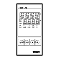
For change of display
For action of function setting
Up down key for change of setting value.
Holding the U/D keys changes value at a rapid rate.
Measured value indication,Charactor indication
F KEY
M KEY
▲▼KEY
PV
Set value indication,Operation quantity indicationSV
Output monitor(appears when OUT1 is ON)OUT
Alarm1 monitor(appears when EV1 is ON)AL1
・
When fitting the product,give more than 12 mm space between the upper / lower / left & right
・
Install the unit in either horizontal or vertical ( upward ) direction.
①
②
③
④
⑤
⑥
⑦
⑧
⑨
⑩
OUT1
SSR Driving Voltage Output DC12V
② ③
② ③
+ -
OUT2/EV2
Relay Output AC250V 1A (Load resistance)
Relay Output AC250V 3A (Load resistance)
① ⑥
POWER SUPPLY
100 to 240V AC 50/60HZ 6VA
(NO polarity)
④
⑤
EV1
⑦ ⑥
Temp. INPUT
RTD
⑧
⑨
⑩
b
B
A
TC
⑧
⑨
⑩
-
+
Exactly same potential wires for EV1 and EV2
circuits can be connected.
※
Terminal
⑥
・
Do not touch the terminal part while the power is on.
AC100 to 240V, 50/60Hz
85% to 110% of the rated voltage
Operating Voltage Range
Input Power Requirments
6VA MAXPower Consumption
EEPROMMemory Element
a) Thermocouple Input ( type
:
K,J,R,T,N,S,B )
b) 3-wire Resistance Temperature Detector Input ( type
:
Pt100,JPt100 )
(Changeable by input type selection)
3 kinds of PID,ON/OFF
Input of Sensor
Control Method
a) Relay Contact Output AC250V 3A MAX
b) SSR Driving Voltage Output DC12V 600
Ω(ormore)
( Output type depends on the model. )
OUT1 (Control Output )
Relay Contact Output AC250V 1A MAX
Relay Contact Output AC250V 1A MAXOUT2 / EV2 ( Option )
Event1
0 to 50
℃
, 20 to 90
%
RH ( Avoid making of dew )
-25 to 75
℃
, 5 to 95
%
RH ( Avoid making of dew )
Operation Environment
Storage Environment
Less than 100 gms.Weight
Overvoltage Category
Ⅱ
Installation Environment
Keep away from the following
:
・
Gas of corrosion,dust and oily smoke.
・
The electrical noise of the generator.
・
The influence of electromagnetic field.
・
Mechanical vibration and shock.
・
The direct sunlight.
Location of the Unit Setting
Installation Attachment
Watertight packing
※This
packing is not attached
・
The use of Noise Filter close to the Power Supply terminal is recommended.
Recommended Noise Filter
:
RSEL-2002W/A
(
available from TDK Lambda
)
Noise filter's terminal 3 and 4 should be connected to the unit.
Noise filter's body may or may not to be connected to frame ground. Both are acceptable.
・
Make sure the wiring is done correctly for any wires with polarity ( + and - ).
・
For relay contact output, “C : common” and “NO : normal open” .
・
Temp.INPUT and OUT1 in case of SSR Output,only the secondary circuits
with reinforced/dual insulation from the primary side can be connected.
・
A conformity wire : copper / AWG18-24 / Temp.rating 80
℃
・
Use specified size (M3.5 width 7.3 mm or less) crimped terminals for wiring and
machines & tools.
・
Tightening torqe : 0.5 Nm ( 5
kgfm, 4.43 lb.fin)
CAUTION BEFORE CONTROL
PID Control
Better control result is achieved as opposed to that of ON/OFF control.
Life span of relay is shorter,as output exists freduently with relay contact.
Merit
Demerit
Merit
Demerit
ON/OFF Control
Life span of relay is generally longer,as it is ON when temperature is below SV
and it is OFF when temperature is over SV ( For heating control ).
Control value is worse in comparison with that of PID control.
・
Setting program is stored after power OFF,as non-volatile memory is equipped with
・
Either thermocouple or R.T.D ( Pt100 / JPt100 ) is selectable input type.
For suitable apprication,please select most appropriate input type and adjust input setup.
・
PID or ON/OFF control is selective for the optimal performance and each detail of features is
specified in the table as bellow.
TTM-i4N SERIES controllers for setting storage.
NO C
NO CNO C
When having the purchased controller at hand,please be sure that its correct model.
See the following “Model Configuration” .
The following symbol marks provide to prevent incident or damage.Kindly refer to the details
of the WARNING/CAUTION when using for the first time.
For prevention of its malfanction,do not push the front key with sharp points.
Spare terminal must not be used for other purposes.
CAUTION
Make sure the correct wiring connection before turning on electricity.
Mis-wiring may cause malfunction of the unit and fire.
Never modify the unit to prevent damage or incident such as malfunction and fire etc.
・
Please put this user's manual aside for your reference,when operating the unit.
・
Copy or reprint of this manual,wholly or partially,is not allowed.
・
The contents of this manual may change without notice in future.
WARNING
INSTALLATION CONDITIONS
・
Indoor use
・
Altitude up to 2000m
・
Pollution Degree 2
・
Installation Attachment ( For installation,please see “PANEL CUTOUT & INSTALLATION” on the right.)
・
This user's manual : 1 copy
Code
・
This product is intended for use with industrial machineries,machine tools and measurement
instruments.(It is not to be used with medical equipment which involves human lives).
CAUTION
& backface portion to the product and the peripheral device or plates.
・
When you use compressed lead wire to install multiple units,please be careful sufficiently
not to touch the other lead wires.
CAUTION
Relay Output AC250V 1A (Load resistance)
WARNING
・
This Controller is not equipped with overcurrent protection device ( Fuse ).
when making power source wiring. A Fuse is connected to the live side.
Please prepare semi-time lag fuse ( rated voltage : 250V, rated current : 1A )
48
( 2)
4 59
48
Single Unit Istallation
Multiple Unit Installation
45
+0 .6
0