Do you have a question about the Toho Electronics TTM-J4 Series and is the answer not in the manual?
Highlights potential dangers like electrocution, skin burns, unit damage, or minor operator injury due to mishandling.
Emphasizes correct wiring before power-on to prevent malfunction, fire, and damage. Advises against using sharp points on keys.
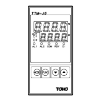
Identifies key components and their functions: PV, SV, OUT1, OUT2, AL1, AL2, RDY indicators, and MODE, FUNC, ▲, ▼ keys.
Instructions to verify the correct model and check for included accessories like the installation attachment and user's manual.
Details TTM-J4/J5 model dimensions and output types (Relay, SSR drive voltage), including standard alarm/output configurations.
Provides detailed dimensions and panel cutout specifications for TTM-J4 and TTM-J5 models for installation.
Illustrates wiring connections for TTM-J4 and TTM-J5 units, including power, input, outputs (OUT1, OUT2/EV2), and alarms (EV1).
Explains the choice between PID and ON/OFF control, highlighting their merits and demerits for optimal performance.
Outlines the fundamental operational sequence, including power-on status, setting modes, and key press actions.
Details the navigation through various setting menus (e.g., Initial Setup, Control Setup, Event Outputs, Timer, Display) using MODE, FUNC, and Arrow keys.
Explains how to adjust specific parameters like input type, control output, alarm settings, and PID constants using the keys.
Provides solutions for common issues such as incorrect input values, display errors, or communication problems.
Details specific key press sequences for releasing timer settings, resetting, or initiating self-tuning for troubleshooting.
| Control Method | PID control |
|---|---|
| Number of Control Outputs | 1 |
| Number of Alarms | Up to 2 |
| Communication | RS-485 (optional) |
| Ambient Temperature | -10 to 50°C |
| Input Type | Thermocouple, RTD |
| Output Type | Relay, Voltage pulse, Current |
| Power Supply | 100 to 240 VAC |
| Display | LED |
| Alarm Output | Relay |
| Control Output | Relay, Voltage pulse, Current |