●Bank function
8 banks each with 16 setting that can be changed as optional parameter.
A desired state can be reached by adjusting the bank setting, but without modifying the
temperature setting or valve of the PID.
This can be done by setting up a parameter for an applicable bank that references the
temperature control for one unit.
Bank8
1
2
3
4
・
・
・
16
Optionalparameter
settingof16types
Bank3
1
2
3
4
・
・
・
16
Optionalparameter
settingof16types
Bank2
1
2
3
4
・
・
・
16
Optionalparameter
settingof16types
Bank1
1
2
3
4
・
・
・
16
Optionalparameter
settingof16types
●Remote SV
Signals from external sources become the controller parameters.
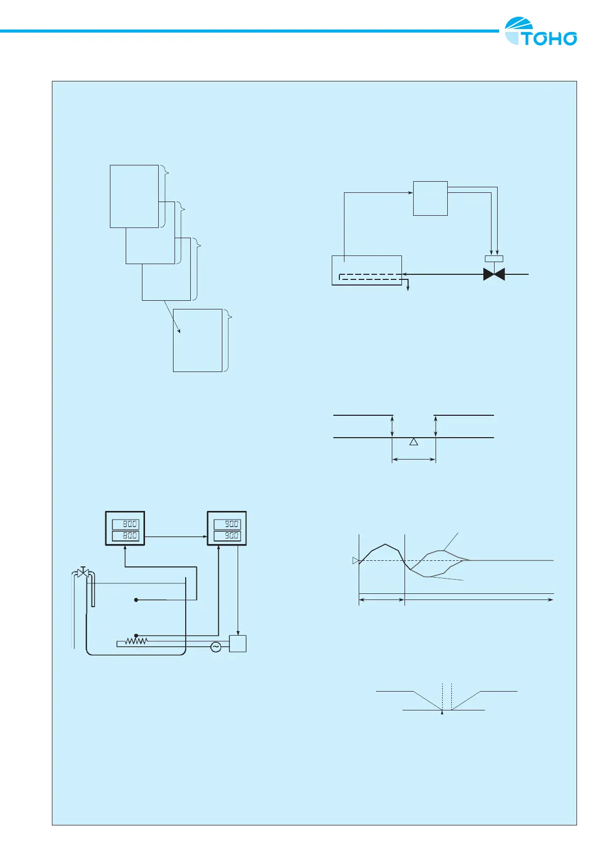
・Cascade control using remote SV
Cascade control is where the control signal for a single controller is applied to other
controllers, and the controller that receives control signals from an external source
convert those signals into parameters for control purposes.
As shown in the illustration above, cascade control can be achieved with the use of two
controllers.
TTM-204/205/207/209 TTM-205/207/209
Watertanktemperature Heatertemperature
Controloutput
Heatercontroltemperature
(remoteSV)
Heater
SSR
Controller Controller
●Position proportional control
■Position proportional control
・According to the operation amount required for PAD control, the valve opening is
changed by outputting an open signal or close signal to the valve on the basis of the
valve motor stroke time, so that the ow rate is adjusted, thereby controlling the target
temperature. The control can be exerted without feedback resistance.
・The valve motor stroke time means the time from the full opening of the valve till its full
closing.
Controller
Opensignal
Closesignal
Controlobject
Warmwater
Sensor
Warmwaterdrain
Warmwater
Valve
・Valve motor drive dead band
In position proportional control, the open signal or close signal is output so that the
operation amount of the regulator may agree with the opening of the valve.
It is necessary to refrain from performing an open/close changeover operation frequently
in consideration of the service life of the valve.
A dead band is provided at the open signal/close signal output changeover point.
In this area, both open signal output and close signal output are stopped to reduce
frequent open/close changeover operations.
Closesignal
Openrate
Deadband
MV
Opensignal
・Initial opening after the end of AT
It is possible to set the operation amount just after the end of auto tuning in order to
restrict undershoot just after this end.
Example) Response after the end of AT
DuringAT
Temperature
Initialopenrate=100%
Initialopenrate=0%
Normalcontrol t
●Heating and cooling
 Loading...