●Improvement of the controllability with new PID
algorithm
①Time until it is stabilized from a control start is shortened
②Loading the jump less control which controls the overshoot after
the disturbance
③You can chose from three kind of PID control that can be chosen
●Full multiple inputs
Established the input specication to be one type of the thermocouple
(13 types), the platinum resistance temperature sensor (2 types),
voltage (5 types) and the electric current (1 type). (Modification of
setting with parameter)
●Sampling period
Realized acceleration in 200mS
●Utilizes a liquid crystal display
①The indication range has been extended to present 5 columns
②Actualized the various indication with 11 segments
③Adopted LED to back light
●PV color auto-change
Display color of Process value (PV) can be optionally set from Red,
Orange and Green as compare with Setting value (SV).
●Compact size
Depth is compact size, TTM-204 is only 55mm, and TTM-205, 207 and
209 are also only 65mm.
●Loader communication function
The best for the setup work of a parameter
Cable: Option (sold separately)
Software: Free option ---- It can download from our web site
●Abundant output type
Relay contact, SSR-driving, Open collector, Voltage (5 types) and
Electric current
●Substantial option function
①CT input (Max. of 2 points) ②Event input (Max. of 4 points) ③Event
output (Max. of 7 points. However, when 7 points are used, you can
not use the control output.)
●External standards
We have acquired "CE", "UL" and cUL.
●Protection structure (Available only for TTM-204)
Corresponding to "IP66"
●Valve position proportionality control
The function carries out valve position proportionality control without
feedback resistance.
●Two choices of case colors (Available only for TTM-204)
"Black" or "Gray" choice is possible to preference
●Blind function
The system can be configured so that only specific, selected
parameters are displayed from set of parameters.
●Simple timer function (independent three points)
The order of "After the dened time period passes, the control starts
or stops" can be controlled by one unit.
Also use by the timer independent is possible. (Event output ON/OFF)
●Priority screen
Without showing a parameter screen, a display and a setup can
be performed by indicating a necessary parameter screen on the
operation mode screen.
(Maximum of 16 screens)
●Digital PV lter
Corresponding to the sudden change of input value, it can apply the
lter with the software
●Manual control
A manual output function enables application of various
instrumentation systems
●Communication function
(RS485: An exclusive protocol / MODBUS)
The range extends up to the distance of 500m, and can connect up to
31 units concurrently.
With one host computer, it can remote consolidate watching "The
collection of the data" and "Change of each setting value" at the place
where it is far.
●Soft-start function
When the power supply is turned on, limitation can be put on
manipulated value during specic time in PID control.
●Delay timer (Available only ON/OFF control)
It is possible to make the action of control output (Main or auxiliary)
delay during specific time (setting). This can be used to protect the
freezer.
●Loop Error
This monitors the measured values and operation time in order to
detect errors in the control loop.
■Features
DIGITAL
CONTROLLER
TTM
-
200
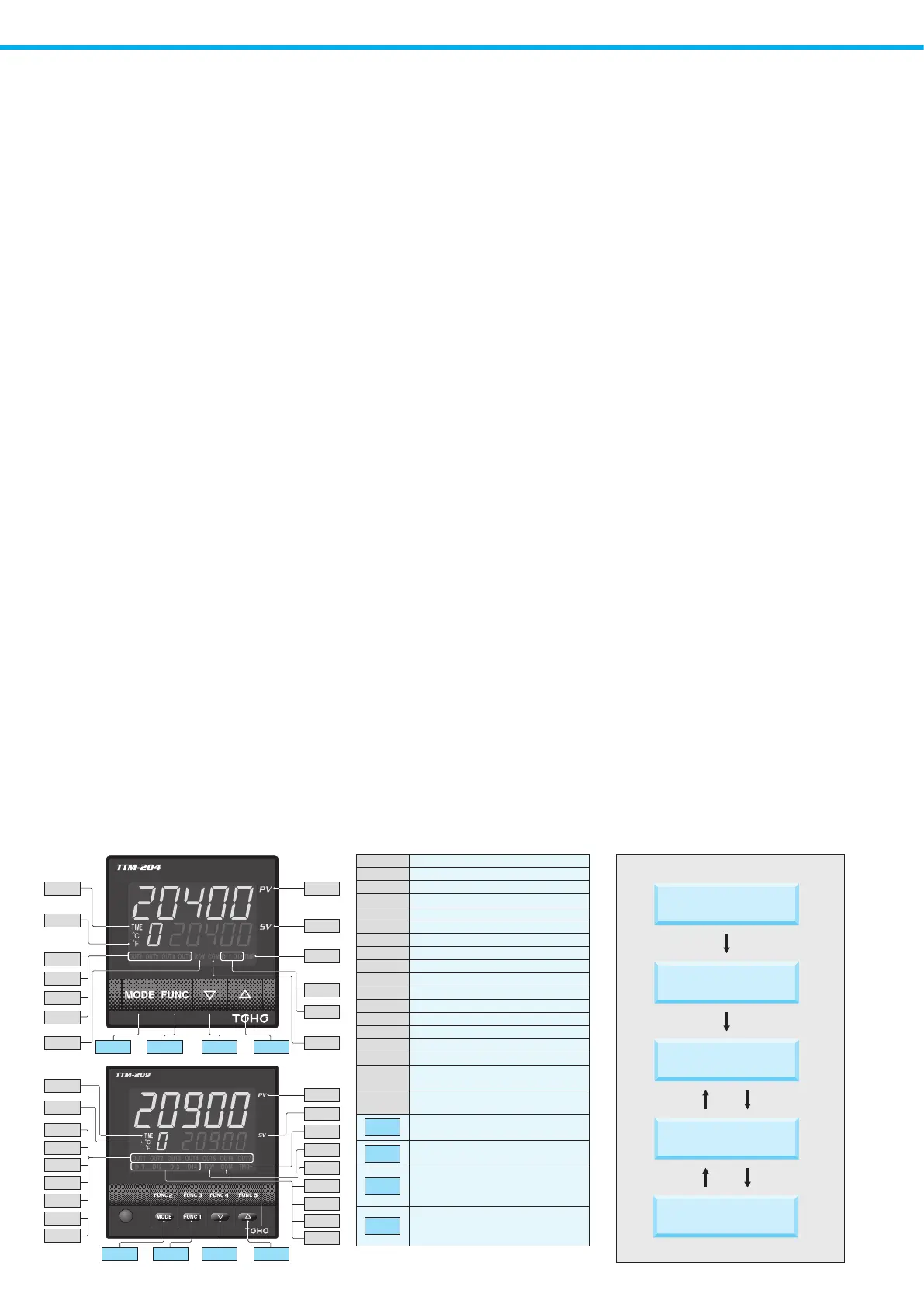
■Operation ow■Front Panel
OUT1 Output1 monitor (It appears when output)
OUT2 Output2 monitor (It appears when output)
OUT3 Output3 monitor (It appears when output)
OUT4 Output4 monitor (It appears when output)
OUT5 Output5 monitor (It appears when output)
OUT6 Output6 monitor (It appears when output)
OUT7 Output7 monitor (It appears when output)
RDY RDY lamp (It appears in the state of Ready)
COM
COM lamp (It blinks during communication)
DI1 DI1 monitor (It appears when DI1 operates)
DI2 DI2 monitor (It appears when DI2 operates)
DI3 DI3 monitor (It appears when DI3 operates)
DI4 DI4 monitor (It appears when DI4 operates)
TMR TIMER lamp
(It appears when timer operates)
TIME It appears when the setting is "Timer"
℃/°F
It appears when the setting is "Temperature"
PV
Measured value indication, Character
indication, Timer set-up time indication
SV
Set value indication, Operation quantity
indication, Timer remaining time indication
MODE
Mode key
It is used when changing a screen.
FUNC
Function key
It executes the function that is set
▲
Up key
It is used when making a setting value increase
It is used when changing input setting mode
▼
Down Key
It is used when making a setting value decrease
It is used when changing parameter screen
※OUT6 is not available for TTM-207.
TIME
℃
OUT1
OUT2
OUT3
OUT4
PV
SV
DI2
DI1
TMR
RDY
COM
FUNC
▲▼
MODE
TIME
℃
OUT1
OUT2
OUT3
OUT4
OUT5
OUT6
OUT7
FUNC
▲▼
MODE
PV
SV
COM
RDY
DI1
DI2
DI3
DI4
TMR
Powersupplyturningon
Initialscreen
Operationmode
Setupitemchoicescreen
SET1toSET20
Eachsetting
ModeKey
twoseconds
Modekey
twoseconds
ModeKey
twoseconds
Modekey
twoseconds
 Loading...