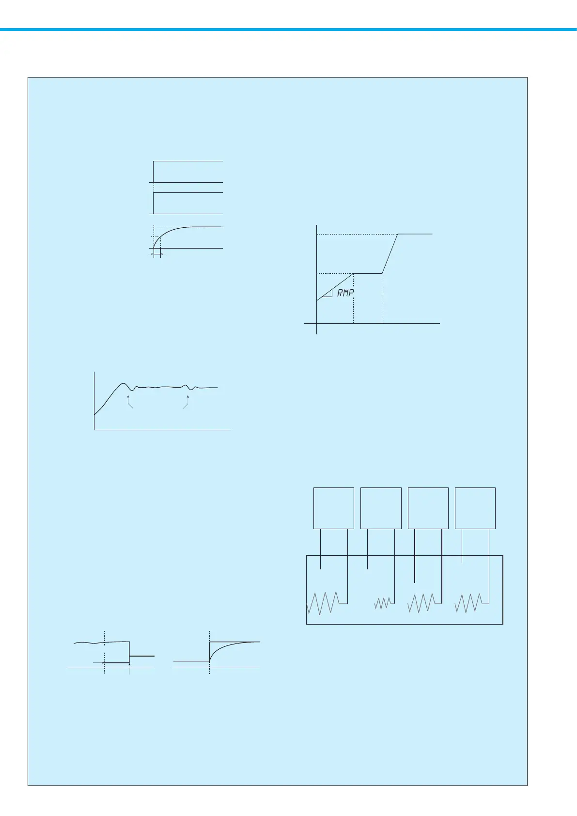
●Digital PV lter
It is the function to realize the CR lter eect on the software by performing primary delay
operation to the measured value (PV).
The eect of the lter can be set by the time constant.
(Time constant is the time that the PV value reaches up to about 63% when the input
changes on the step.)
Time
0%
100%
Inputsignal
Time
0%
100%
Time
Timeconstant(t)
0%
100%
63%
Readinginput
NoDigitalPVfilter
Timeconstant(t)=0
Readinginput
WithDigitalPVfilter
Timeconstant(t)>0
The use of Digital PV lter
1) Removal of high frequency noise --- The inuence of a noise when an electric noise
joining an input is mitigated.
2) A response can be delayed against the sudden change of the input.
●Self-tuning PID
Executionofself-tuning
(Self-tuningON)
①
①Atthetimeofsettingvaluechange
②Atthetimeofthetemperaturechangebydisturbance,
andatthetimeofhunchinggenerating
②
Temp.
Time
●Auto (RUN) / Manual function
The auto control and the manual control, they can be switched by the front key.
Manual operation is the function that is not concerned with the situation of a deviation,
but can set up and output the output for control arbitrarily (manipulation variable).
The system can be operated manually in the time of the system trial run and so on, when
to check of nal control element (a valve, heater, etc.) of operation is performed, when
the sensor breaks down by any chance, or when usual control can't be done.
There is the Balance-less Bump-less function, which holds down sudden change of control
output when switching the automatic control and manual control mutually. Furthermore,
it stops damage on the peripheral equipment by sudden change and the bad inuence to
a control system. So, you can operate in comfort.
Autocontrol Autocontrol
Previous
manipulatedvariable
Manipulated
variablemodification
Switch Switch
Manualcontrol Manualcontrol
Balance-lessBump-less
Balance-lessBump-less
Balance-less Bump-less
●Ramp function
The ramp function is a matter of function made to have inclination against the change in
SV (Setting value).
As actual operation, the setting value of a dummy is made to change gradually toward
the setting value after changing. Then it controls to the setting value of the dummy.
The amount of change for around one minute of SV is set up.
When a rapid change of the control result is not allowed with the characteristic of the
control subject, and when the change course (inclination) of the control result becomes
important in a control subject, the eect of a ramp function is demonstrated, the eect of
the ramp function is demonstrated.
In addition, since only SV is changed, the result expected may not be obtained when it
expects great inuence to PV (measured value).
SV
SV
Set-uptime
Time
1min
*Asetupbythebankfunctionispossible.
ByvariationsetasRMP,asettingvalue
is changed from the temperature at
thetimeofstartingbeforeSV.
●Simultaneous temperature rise function
■Simultaneous temperature rise
・When simultaneous temperature rise control is exerted by multi-channels using the
RS-485 communication function, a master and slave are determined beforehand.
This permits reaching the respective goal values at the same time regardless of the
characteristic of each channel.
The channel, in which the time from the start of control to the reach to the goal value is
the longest, is specied as a master. The other channels are specied as slaves.
・The simultaneous temperature rise function is started at the start of run (including the
power ON time) or a change of setting value, and is ended when the master reaches
the goal value.
Controller1ch
Input Output
Sensor
Heater
Controller2ch
Input Output
Furnace
Sensor
Heater
Controller3ch
Input Output
Sensor
Heater
Controller4ch
Input Output
Sensor
Heater
◦How to use
1. Perform communication protocol settings to the TOHO protocol.
2. In the communication changeover setting, set the channel, in which the temperature
reaches the goal value latest, to the simultaneous temperature rise master, and then
set the other channels to the simultaneous temperature rise slaves.
3. Set the main control sensitivity.
During a simultaneous temperature rise, the slave side exerts ON/OFF control for the
current temperature of the master. Accordingly, set the sensitivity to a level that does
not cause chattering.
Note: Precautions on use
1. Perform auto tuning for each channel as required.
2. When using the simultaneous temperature rise function, do not perform communication
with the outside.
 Loading...