EasyManua.ls Logo

Toky AI208 Series User Manual

Toky AI208 Series
10 pages
To Next Page IconTo Next Page
Page #1 background imageLoading...
Page #1 background image
1/10page KKAI208C01A-A1-20140904
AI208 Series Temperature Controller User Manual
Optional input signal types and models
With many functions of measured display,control output,alarm
output,analog output,RS485 communication,etc.
Optional many types of PID arithmetic and with auto-tuning function.
Using for industrial machinery, machine tools,measuring instruments.
Economical and easy operation.
Features:
The instruction explain instrument settings, connections,name and etc,please read carefully before you use the temperature controller.
Warning
1When the failure or abnormal of products lead to a system of major accidents,please set the proper protection circuit in the external.
2Please don`t plug in before completing all the wire.Otherwise it may lead to electric shock, fire, fault.
3Not allow to use outside the scope of product specification,otherwise it may lead to fire,fault.
4Not allow to use in the place where is inflammable and explosive gas.
5Do not toch wire connectors when the power on,otherwise you may get an electric-shock.
6Do not remove,repair and modification this product,otherwise it may lead to electric shock, fire, fault.
Caution
1The product should not be used in a nuclear plant and human life associated medical equipment.
2The product may occur radio interference when it used in home.You should take adequate countermeasures.
3The product get an electric shock protection through reinforced Insulation. when the product is embedded in the devices and wiring,please subject to the
specification of embedded devices.
4In order to prevent surge occurs,when using this product in the place of over 30m indoor wiring and wiring in outdoor,you need to set the proper
surge suppression circuitry.
5The product is produced based on mounting on the disk.In order to avoid to touch the wire connectors,please take the necessary measures on the product
6Be sure to observe the precautions in this manual, otherwise there is a risk of a major injury or accident.
8To prevent to damage the machine and prevent to machine failure, the product is connected with power lines or large capacity input and output lines
and other methods please install proper capacity fuse or other methods of protection circuit.
9Please don't put metal and wire clastic mixed with this product,otherwise it may lead to electric shock, fire, fault.
10Please tighten screw torque according to the rules.If not,it may lead to electric shock and fire.
11In order not to interfere with this products to dissipate heat, please don't plug casing around the cooling vent hole and equipment.
12Please don`t knock or rub the panel with rigid thing.
13The readers of this manual should have basic knowledge of electrical,control, computer and communications.
14The illustration, example of data and screen in this manual is convenient to understand,instead of guaranteeing the result of the operation.
15In order to use this product with safety for long-term,regular maintenance is necessary. The life of some parts of the equipments are by some restrictions,
but the performance of some will change for using many years.
16Without prior notice, the contents of this manual will be change. We hope these is no any loopholes, if you have questions or objections, please contact us.
1.Installation
1This product is used in the following environmental standards.
IEC61010-1[Overvoltage categoryⅡ、class of pollution 2]
2This product is used in the following scope:surrounding environment, temperature, humidity and environmental conditions.
Temperature050℃;Humidity4585%RH;Environment conditionIndoor warranty,The altitude is less than 2000m.
3Please avoid using in the following places:
The place will be dew for changing temperature;with corrosive gases and flammable gas;with vibration and impact;with water, oil, chemicals, smoke and steam
facilities with Dust, salt, metal powder;and with clutter interference, static electric and magnetic fields, noise;where has air conditioning or heating of air blowing
directly to the site.
4On the occasion of the installation, please consider the following before installing several.
In order to protect heat saturated, please ensure adequate ventilation space.
Please consider connections and environment,and ensure that the products below for more than 50mm space.
Please avoid to installed over the machine of the calorific value(Such as heaters, transformer, semiconductor operations, the bulk resistance).
When the surrounding is more than 50, please using the force fan or cooling fans.But don't let cold air blowing directly to the product.
In order to improve the anti - interference performance and security, please try to stay away from high pressure machines, power machines to install.
Don`t install on the same plate with high pressure machine and the product.
The distance should be more than 200mm between the product and power line.
Caution of Install & Connection
Question and Answer IconNeed help?

Do you have a question about the Toky AI208 Series and is the answer not in the manual?

Toky AI208 Series Specifications

General IconGeneral
Input TypeThermocouple, RTD, Analog
OutputRelay, SSR, Analog
DisplayLED
Power Supply100-240V AC or 24V DC
Resolution0.1°C
CommunicationRS485 (optional)
Control ModePID Control
Dimensions48x48mm or 96x96mm

Summary

Safe Caution

Warning

Safety warnings for product usage, including electrical hazards and fire risks.

Caution

General cautions for product usage, covering interference, damage prevention, and operational risks.

Caution of Install & Connection

Precautions for installation environment, ventilation, wiring, and electrical safety.

Cable Caution

Cable Usage Precautions

Guidelines for selecting and using specified compensation wires and avoiding noise interference.

Model Illustration

Model Designation

Explanation of the AI208 series model naming convention and input signal types.

Ordering Information

Model Configurations

Table detailing model options for control output, alarm, and communication interfaces.

Specifications

Electrical Parameters

Technical specifications for electrical characteristics: sample rate, power supply, consumption, and insulation.

Measured Signal Specifications

Details on input types: TC, RTD, mV, mA/V; measuring ranges, resolution, accuracy, and impedance.

Isolation Diagram

Diagram illustrating isolation between power supply, MCU, relay, and communication ports.

Panel Overview

Universal Panel Name

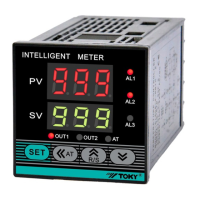
Labels and functions of buttons, indicators (OUT1, OUT2, AL1, AL2, AT), and display windows.

Operation Process & Method

Operation Process and Method

Step-by-step guide for navigating menus, changing settings, and using control modes.

Menu Description

Menu Item Details

Explanation of menu items: PV, SV, P, I, D, SPD, OVS, DB, CP, etc., with ranges and factory settings.

Alarm Parameters and Logic

Alarm Parameters and Output Logic

Details on alarm types (absolute, deviation, interval) and their relation to output logic diagrams.

Alarm Extension Function Table

Table describing alarm handling for AE1/AE2 values, including alarm state and remarks.

Key Function Operation

Key Function Operation

Instructions for monitoring mode, PID parameter identification, auto-tuning, and PID/cooling control.

Signal Linear Auto-Tuning

Procedure for calibrating input signals (e.g., TC, RTD, mA, V) using auto-tuning.

Dimension

Panel and Hole Dimensions

Table detailing panel sizes (e.g., 48*48, 96*96) and corresponding hole dimensions.

Connections

Wiring Diagrams

Schematic diagrams for A1208-4, A1208-6, A1208-7, A1208-8, A1208-9 models.

Simple Fault Diagnosis

Method for checking input disconnection and signal integrity using display values.

Communication Protocol

Modbus RTU Communication

Details on Modbus RTU half-duplex, function IDs, data frame format, and CRC check.

Abnormal Communication Handling

Information on error codes (e.g., 0x02, 0x03) and responses for abnormal communication.

Communication Cycle Time

Explanation of communication cycle time calculation and baud rate impact.

Data Registers

Reading Registers

Guide on reading integer SV values using Modbus RTU, including ADD codes and data transformation.

Writing Registers

Procedure for writing float integer SV values using Modbus RTU, with examples.

Address Mapping

Meter Parameter Address Mapping

Table mapping variable names (SV, AL1, AL2) to ADD mapping, register, and R/W status.