33
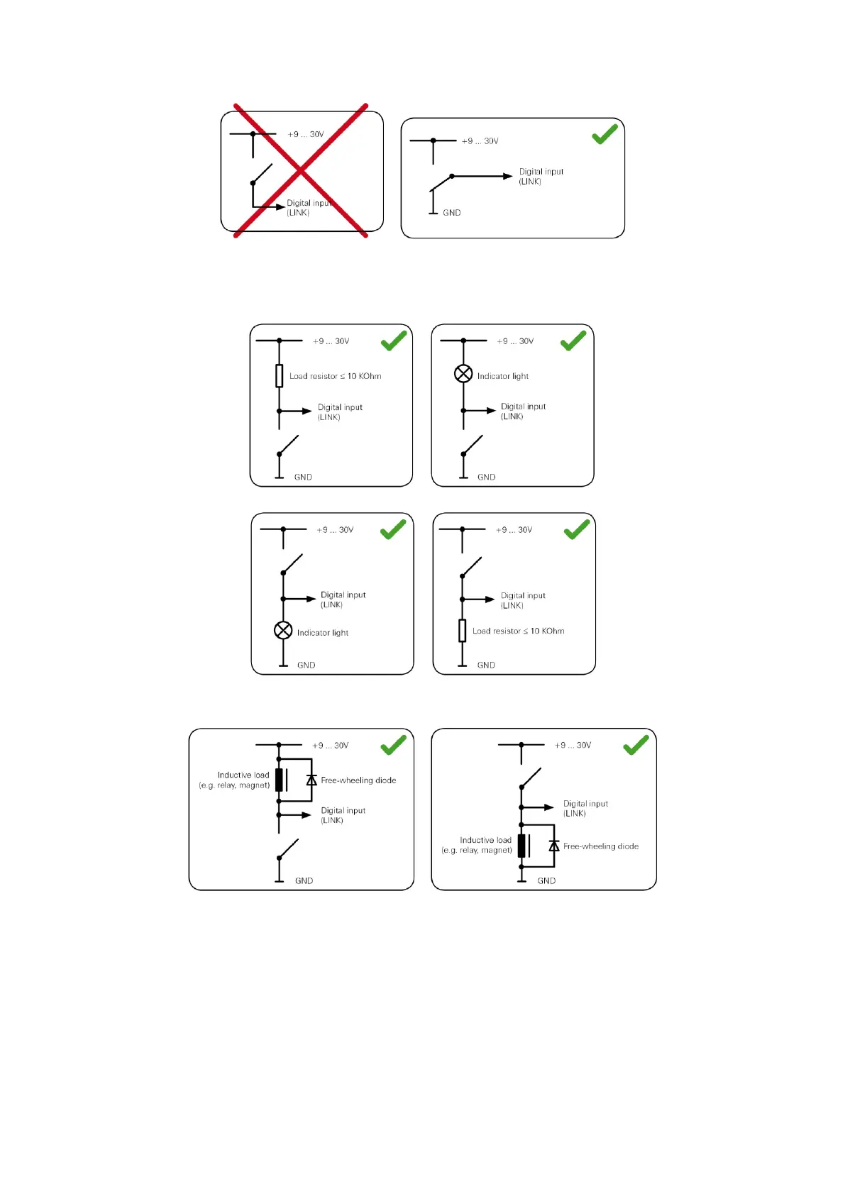
If no change-over switch is available, an electric load for example, indicator light or resistor,
between the digital input and ground (GND) or between the digital input and the vehicle voltage
(+9 ... 30V) can offer defined levels.
When using inductive loads, a free-wheeling diode must be used in parallel with the load.
Wiring the digital output
The digital output OUT of the LINK 510 is an open drain output linking to ground. The connected
load must be connected between vehicle voltage and OUT. Loads requiring more than 0.35 A
must be controlled with relays. If the load requires more than the maximum output voltage use a
12 V/24 V relay, depending on the operating voltage.