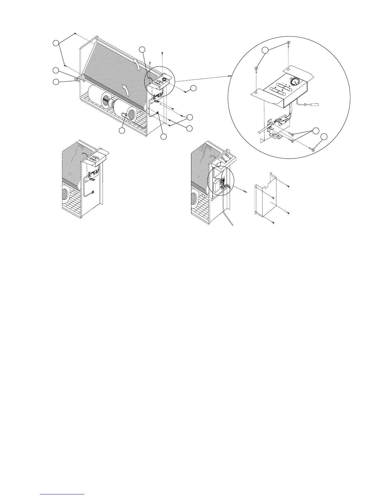
INVERSIONE ATTACCHI BATTERIA - INVERTING THE BATTERY ATTACHMENTS -
UMKEHRUNG AGGREGATANSCHLÜSSE - INVERSION EMBOUTS BATTERIE - INVERSIÓN CONEXIONES BATERÍA
A - Smontare il quadro dei comandi
elettrici.
B - Scollegare il connettore dei cavi
motore POS. 9.
C - Smontare il termostato di consenso
POS. 4 estraendolo dalle alette della
batteria.
D - Allentare leggermente le viti di
fissaggio del basamento motore POS.
10, rimuovere le viti di fissaggio della
batteria POS. 6; prenderla alle due
estremità estraendola nel senso indicato
dalle frecce (facendo attenzione a non
deteriorare l'isolamento) ruotarla di
180°, riposizionare gli attacchi dal lato
opposto e bloccare nuovamente le viti
POS. 10.
E - Invertire la collocazione del tappo
di scarico condensa POS. 7 e invertire
la posizione della vaschetta raccolta
condensa POS. 8 se presente.
F - Smontare il connettore dei cavi
motore dal fianco dx e rimontarlo
nell'apposita sede del fianco sx.
G - Montare il quadro dei comandi
elettrici sul lato opposto , ripristinare i
collegamenti elettrici (vedere schema
allegato).
H - Inserire il termostato di consenso
(o sonda) , tra le alette della batteria ,
in pos. opposta rispetto alla precedente
; se è presente il termostato aria
ambiente riposizionare il bulbo (o
sonda) con gli appositi fissaggi POS. 3.
A - Dismantle the electric control
panel.
B - Disconnect the motor lead
connector - POS. 9.
C - Dismantle the consent thermostat
POS. 4 pulling it out from the battery
fins.
D - Loosen the motor base fixing
screws POS. 10, remove the battery
fixing screws POS. 6; hold the battery
at both ends and pull it out in the
direction of the arrow (taking care not
to damage the insulation), rotate the
battery by 180° , replace the
attachments on the opposite side and
tighten the screws POS. 10.
E - Invert the position of the
condensation outlet plug POS. 7 and
the position of the condensation tray
POS. 8, if fitted.
F - Dismantle the motor connection
lead from the right side and fit it to the
housing on the left side.
G - Reassemble the electric control
panel on the opposite side, connect the
electric leads (follow the wiring
diagram).
H - Place the consent thermostat (or
probe) between the battery fins, in the
opposite position from before; if the
room air thermostat is fitted, position
the bulb (or probe) with the special
fixings POS. 3.
A - Die Schalttafel der elektrischen
Steuerungen abnehmen.
B - Den Stecker der Motorkabel
herausziehen. POS. 9.
C - Den Freigabe-Thermostat POS. 4
aus den Lamellen des Austauschers
herausziehen.
D - Die Schrauben des
Motoruntergestells POS. 10 lockern,
die Schrauben des Austauschers POS.
6 entfernen; den Austauscher an beiden
Enden anfassen und laut Pfeilrichtung
um 180° drehen und herausziehen (auf
die Isolierung achten); die Anschlüsse
an der gegenüber liegenden Seite
anordnen und die Schrauben POS. 10
wieder festziehen.
E - Die Position des Kondenswasser-
Abflussstopfens POS. 7 und der
Kondenswasser-Sammelwanne POS. 8
(wenn vorhanden) ändern.
F - Den Stecker der Motorkabeln an
der rechten Seite abnehmen und an
dementsprechender Stelle an der linken
Flanke montieren.
G - Die Schalttafel an der
gegenüberliegenden Seite montieren
und die Elektroanschlüsse wieder
herstellen (siehe Schaltplan).
H - Den Freigabe-Thermostat (oder
Sonde) an der gegenüber liegenden
Stelle bezüglich der vorgehenden
Position zwischen die Lamellen des
Austauschers stecken; sollte der
Raumluft-Thermostat vorhanden sein,
die Thermometerkugel (oder Sonde)
mit den dementsprechenden
Vorrichtungen fixieren POS. 3.
A - Dé monter le tableau des
commandes électriques.
B - Débrancher le connecteur des
câbles moteur POS. 9.
C - Dé monter le thermostat de
consentement POS. 4 en le tirant par
les ailettes de la batterie.
D - Desserrer légèrement les vis de
fixation de l’embase moteur POS. 10,
enlever les vis de fixation de la batterie
POS. 6 ; la prendre aux deux
extrémités en la tirant dans le sens
indiqué par les flèches (en faisant
attention à ne pas abîmer l’isolation),
la tourner de 180°, repositionner les
embouts du coté opposé et bloquer à
nouveau les vis POS. 10.
E - Inverser la position du bouchon de
l’évacuateur condensation POS. 7 et
inverser la position de la cuve collecte
condensation POS. 8 si présente.
F - Démonter le connecteur des câbles
moteur du coté dt et le remonter dans
le spécial logement du coté gche.
G - Monter le tableau des commandes
électriques sur le coté opposé, rétablir
les branchements électriques (voir le
schéma ci-joint)
H - Insé rer le thermostat de
consentement (ou sonde), parmi les
ailettes de la batterie, dans la position
opposée par rapport à la précédente ;
si le thermostat air ambiant est
présent, repositionner la boule (ou
sonde) avec les spéciales fixations
POS. 3.
A - Desmontar el cuadro de los mandos
eléctricos.
B -Desconectar el conector de los
cables del motor.
C - Desmontar el termostato de asenso
POS.4 extrayéndolo de las aletas de la
batería.
D - Aflojar levemente los tornillos de
fijación de la base motor POS.10,
quitar los tornillos de fijación de la
batería POS.6; agarrarla en los dos
extremos extrayéndola en el sentido
indicado por las flechas (prestando
atención a no dañar el aislamiento)
darle la vuelta de 180°, posicionar
nuevamente las conexiones por el lado
opuesto y apretar nuevamente los
tornillos POS.10.
E - Invertir la colocación del tapón de
descarga de la condensación POS.7 e
invertir la posición de la bandeja de
recogida de la condensación POS. 8 ,
si está presente.
F - Desmontar el conector de los cables
motor por el lado derecho y montarlo
nuevamente en su alojamiento del lado
izquierdo.
G - Montar el cuadro de los mandos
elé ctricos en el lado opuesto,
restablecer las conexiones eléctricas
(ver esquema adjunto).
H - Introducir el termostato de asenso (
o sonda) , entre las aletas de la batería ,
en posición opuesta respecto a la
precedente; si está presente el
termostato del aire del ambiente
posicionar el bulbo ( o sonda) con los
dispositivos de fijación adecuados
POS.3.
4
3
9
VTP / AB
10
6
6
6
7
8
1
5
2
O
VTP / VB VTP / CBE
21
 Loading...