FIGURE
41
~~mrnrnm
4040·
16
4040·17 4040·18 4040-19 4040-20
mrn~~mrn
FIGURE
.!.t,
FIGURE
43
SANDING
Arm
Saw rotates slower than a router shaper. You must compensate
for this by feeding the work
in
slower. Feed the material
by
hand to
cut
your
desired pattern.
If
you require more than a
l/S"
deep pattern,
repeat the operation as many times as necessary to reach your desired
depth. See
ACCESSORIES
section under
ROUTERS
AND DOVE-
TAIL BITS and under
ADAPTORS
for description and prices
of
necessary accessories.
DISC
SANDING
(FIGURE
44)
'Co
Mount
one
of
the Toolkraft sanding discs No. XM-834, XM-836,
or
XM-837 on the saw
arbor
to convert
your
machine to a disc sander.
See
ACCESSORIES
under
SANDING
DISCS
AND
DRUMS
for
price
and
description
of
discs. Set the rotating
arm
in
the 0° position.
Make a work
support
table
and
fasten
it
to the table top. Feed the
work into the right hand side
of
the disc as shown
in
Fig. 44.
The
guard may be left off for disc sanding work.
GRINDING:
(FIGURE
45)
To
convert
your
Radial
Arm
Saw to a grinder simply attach Tool-
kraft grinding wheel XM-1076 to the saw
arbor
shaft. See ACCES-
SORIES
under
GRINDING
WHEELS
for prices. Locate the rotating
arm
at
the 0° position
and
slide carriage
to
the reat
of
rotating arm
track. Make a tool rest as shown in Fig.
45
from any scrap lumber
approximately 4" wide
x I" thick x 6" long. Remove the fence and
insert the tool rest between the first and second table sections so that
the 0° cutoff groove
is
in the center
of
the tool rest. Raise
or
lower the
cutting head with the elevating
crank
handle until the center
of
the
wheel
is
even with the
top
of
the tool rest. Install the guard and lock
it in position to give
you
your
desired opening. Neyer grind without
the guard.
ROUTING
4040.26
4040·28
4040-29
4040-25
4040-22
4040·21
FIGURE
42
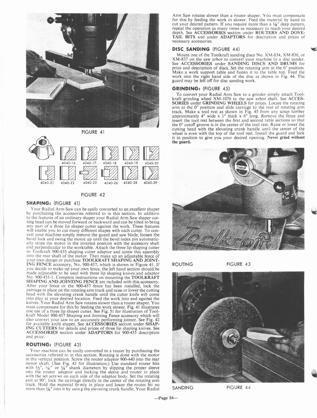
SHAPING:
(FIGURE
41)
Your
Radial
Arm
Saw
can
be easily converted to
an
excellent
shaper
by purchasing the accessories referred to in this section. In addition
to the features
of
an
ordinary
shaper
your
Radial
Arm
Saw
shaper
cut-
ting head can be moved forward
or
backward
and
can
be tilted to bring
any
part
of
a three lip
shaper
cutter against the work. These features
will enable you to cut many different shapes with each cutter.
To
con-
vert
your
machine simply remove the guard and saw blade, loosen the
bevel lock and swing the
motor
up until the bevel index pin automatic-
ally stops the
motor
in the inverted position with the accessory shaft
end perpendicular to the worktable. Attach the three lip shaping
cutter
to Toolkraft 900-435 shaping cutter
adaptor
and screw this assembly
into the rear shaft
of
the motor. Then make up an adjustable fence
of
your
own design
or
purchase
TOOLKRAFf
SHAPING
AND
JOINT-
ING
FENCE
accessory, No. 900-457, which
is
shown in Figure 41.
If
you decide to make
up
your
own fence, the left hand section should be
made adjustable to be used with three lip shaping knives and
adaptor
No. 900-435-1. Complete instructions
on
mounting the
TOOLKRAFf
SHAPING
AND
JOINTING
FENCE
are included with this accessory.
After
your
fence
or
the 900-457 fence has been installed, lock the
carriage in place on the rotating
arm
track and raise
or
lower the cutting
head with the elevating
crank
handle until the cutter knife will come
into play
at
your
desired location. Feed the work into and against the
knives.
Your
Radial
Arm
Saw rotates slower
than
a router shapero You
must compensate for this by feeding the work slower. Fig.
41
illustrates
one use
of
a three lip
shaper
cutter. See Fig.
51
for illustration
of
Tool-
kraft Model 900-457 Shaping and Jointing Fence accessory which will
also convert
your
saw to an aceurately performing jointer. See Fig. 42
for available knife shapes. See
ACCESSORIES
section under
SHAP-
ING
CUTTERS
for details
and
prices
of
three lip shaping knives. See
ACCESSORIES
section
under
ADAPTORS
for 900-435 description
and price.
ROUTING:
(FIGURE
43)
Your
machine can be easily converted to a router by purchasing the
accessories referred to
in
this section. Routing
is
done
with the
motor
in
the
vertical position. Screw the router
adaptor
900-440 into the
rear
motor shaft. (See Fig.
43
for illustration.) Use
standard
router bits
with
1;2",
~6"
or
%"
shank
diameters by slipping the proper sleeve
into the router
adaptor
and
locking the sleeve
and
router in place
with the set sere
ws
on each side
of
the
adaptor
body. Set the rotating
arm
at
90°, lock the
ca
rriage directly
in
the center
of
the rotating
arm
track. Hold the material firmly
in
place
and
lower the router bit no
more than
Vs"
into it by usin g the elevating crank handle.
Your
Radial
-Page
16-
 Loading...