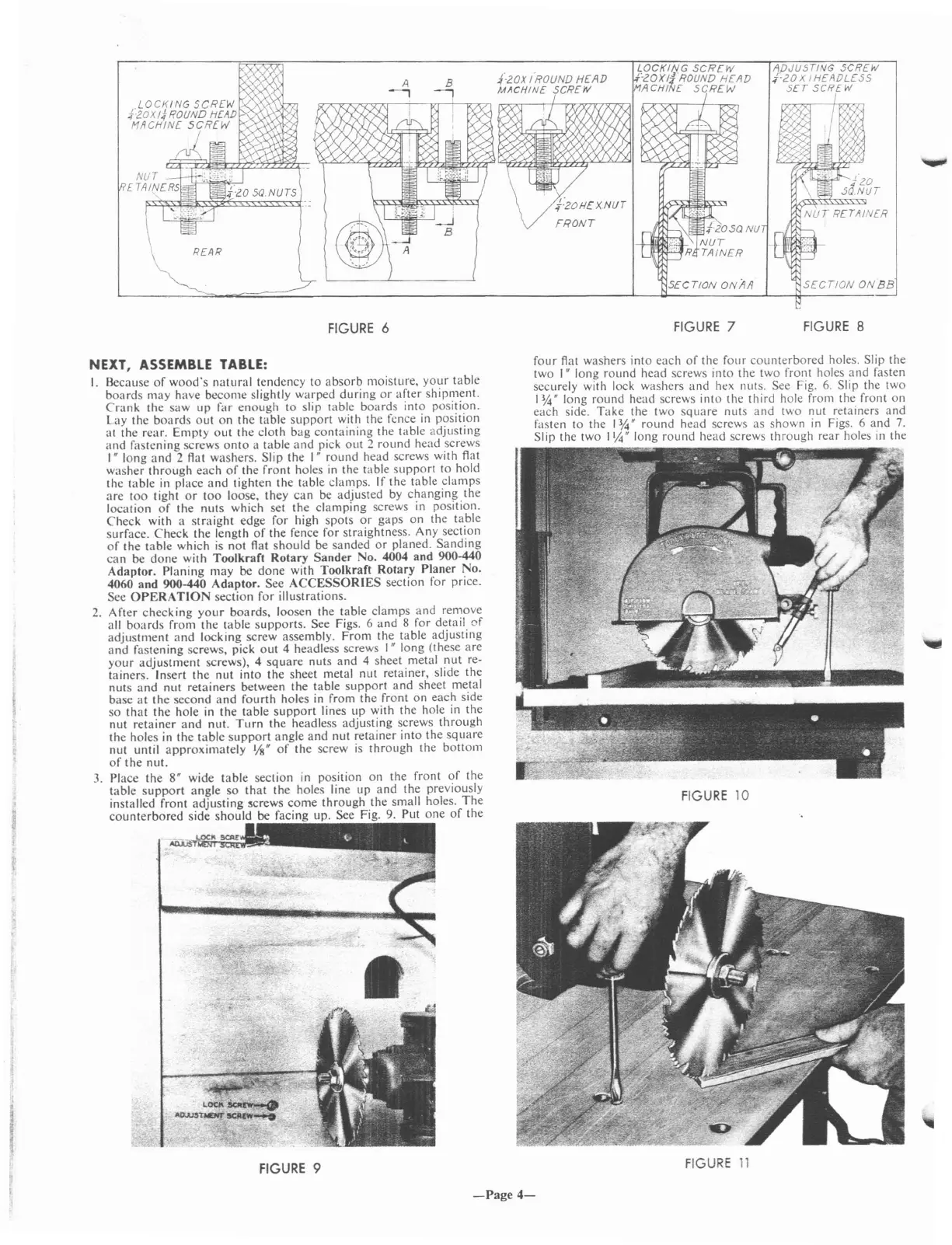
FIGURE
6
FIGURE
7
ADJUSTING
SCREW
;{zox I
HE
ADLE
SS
SET
SCREW
SECTION
ON
BE
FIGURE
8
NEXT,
ASSEMBLE
TABLE:
I.
Because
of
wood's
natural
tendency to
absorb
moisture,
your
table
boards
may
have become slightly warped
during
or
after
shipment.
Crank
the
saw
up far
enough
to slip table
boards
into position.
Lay the
boards
out
on
the table
support
with the fence
in
position
at the rear.
Empty
out
the cloth
bag
containing
the table adjusting
and
fastening screws
onto
a table
and
pick
out
:2
round
head screws
'"
long
and
2 flat washers. Slip the I"
round
head screws with flat
washer
through
each
of
the
front
holes
in
the table
support
to hold
the table in place
and
tighten the table clamps. If
the
table
clamps
are
too
tight
or
too
loose, they
can
be adjusted by
changing
the
location
of
the
nuts
which set the clamping screws in position.
Check
with a
straight
edge for high spots
or
gaps
on
the table
surface.
Check
the length
of
the fence for straightness. Any section
of
the table which
is
not flat
should
be sanded
or
planed.
Sanding
can
be
done
with
Toolkraft
Rotary
Sander
No. 4004 and 900-440
Adaptor.
Planing
may
be
done
with Toolkraft
Rotary
Planer
No.
4060 and 900-440
Adaptor.
See
ACCESSORIES
section for price.
See
OPERATION
section for illustrations.
2.
After
checking
your
boards, loosen the table clamps and remove
all
boards
from the table
supports.
See Figs. 6
and
8 for detail
of
adjustment
and
locking screw assembly.
From
the table adjusting
and
fastening screws, pick
out
4 headless screws
I"
long (these are
your
adjustment
screws), 4
square
nuts
and
4 sheet metal
nut
re-
tainers. Insert
the
nut into
the
sheet metal nut retainer, slide the
nuts
and
nut retainers between
the
table
support
and
sheet metal
base
at
the second
and
fourth
holes in from
the
front
on
each side
so
that
the
hole in the table
support
lines up with the hole in the
nut
retainer
and
nut.
Turn
the headless adjusting screws
through
the
holes in
the
table
support
angle
and
nut retainer into the
square
nut until
approximately
l/S"
of
the
screw
is
through
the
bottom
of
the
nut.
3.
Place the 8" wide table section
in
position
on
the front
of
the
table
support
angle
so
that
the holes line up
and
the previously
installed front
adjusting
5crews
come
through
the small holes.
The
counterbored
side
should
be facing up. See Fig.
9.
Put
one
of
the
FIGURE
9
four
Aat
washers into each
of
the
four
counterbored
holes. Slip the
two I" long round head screws into the two front holes
and
fasten
securely with lock washers
and
ht:x
nuts. See Fig.
6.
Slip the two
I
~"
long
round
head screws into the third hole from the front
on
each side.
Take
the two
square
nuts
and
two nut retainers and
fasten to the
I~"
round
head screws as shown
in
Figs. 6 and
7.
Slip the two \1,4" long
round
head screws
through
rear holes
in
the
FIGURE
10
FIGURE
11
-Page
4-
 Loading...