Disassemble
1. Disconnect tool from air supply and remove all wheels and accessories.
2. Secure tool in a vise with motor axis in horizontal position. Clap onto the dead handle (550-1C) of grinder.
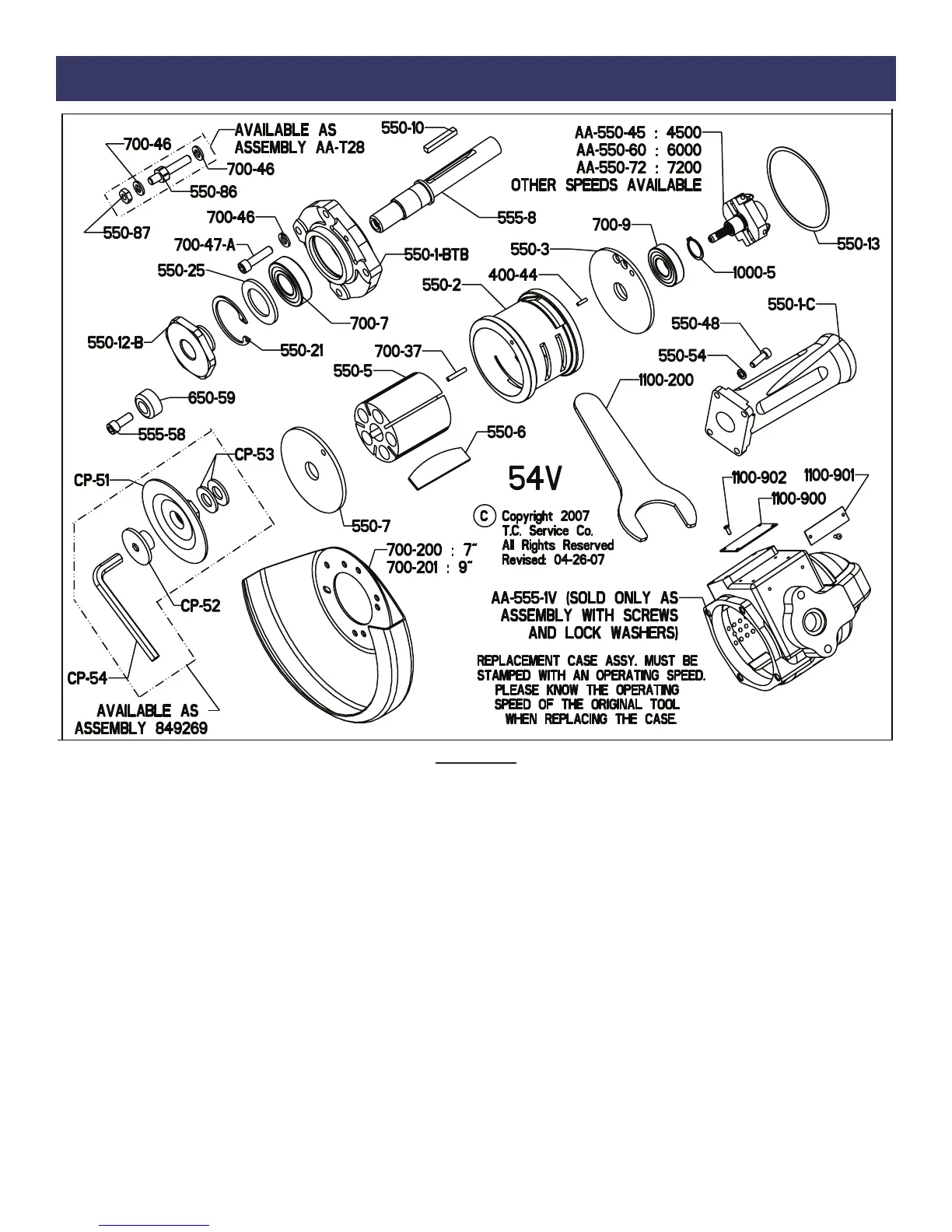
3. Remove four screws (700-47A), four lock washers (700-46) and wheel guard (700-200, 700-201 or 412988).
4. Grasp motor output and pull complete motor assembly from case. The motor assembly must be kept straight to pull from case easily.
Try to maintain alignment as best as possible. Remove case from vise.
5. Secure motor assembly into vise vertically with governor toward upward direction. Clamp onto flats of wheel flange (550-12B).
6. Remove governor (AA-550-XX) with use of governor wrench (1100-825). (Left-hand thread)
7. Remove lock ring (1000-5) with use of snap ring pliers. Remove from vise.
8. Hold motor assembly by the cylinder in one hand. Place a punch in the hole left by the removal of governor. Tap lightly onto the
punch with small hammer. This will drive the spindle (550-8) through the rear bearing (700-9) and rear endplate (550-3). (Take care not
to damage threads inside spindle, or to drop the spindle assemby when it becomes free.)
9. Use a small screwdriver to push the rear bearing out of the rear endplate.
10. Remove the cylinder (550-2), the rotor blades (550-6) and the rotor (550-5). Leave the key (550-10) in the key slot for now.
11. Clamp spindle holder (1100-650) into vise vertically. Align key slot in holder with key of spindle and slide spindle assembly through.
12. Remove wheel flange (550-12B). Remove from vise.
13. Remove key (550-10) and lift off front end plate (550-7).
14. Support front bearing assembly on a suitable drill block. Press spindle (550-8) through front bearing (700-7) with arbor press.
15. Remove snap ring (550-21) with use of snap ring pliers.
16. Lift out bearing cover (550-25).
17. Press out front bearing (700-7) from front bearing support (550-1-BTB).
18. To check throttle valve, unscrew throttle valve cap (700-S-26). Lift out valve spring (600-51) and throttle valve (560-13). Replace
o-ring (200-9) if cracked of torn.
Maintenance
 Loading...