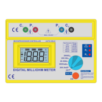
The HellermannTyton TOP TRONIC Model T4137 is a battery-operated digital milli-ohmmeter designed for stable and accurate measurement of low resistance across a wide range of values. This instrument is microprocessor-controlled and features an auto-hold function, making it suitable for various applications requiring precise resistance measurements.
Function Description
The T4137 operates by supplying a low DC constant current to the circuit under test through its C₁ and C₂ terminals (C₁ being positive, C₂ being negative). The voltage drop across the resistance under test is then measured by the potential terminals P₁ and P₂ (P₁ being positive, P₂ being negative). This four-wire measurement method eliminates errors due to the resistance of the test leads and contacts, as well as resistances Rᴀ and Rʙ, ensuring high accuracy, especially for low resistance values. For higher resistance ranges, a simplified two-wire method can also be used by shorting C₁ with P₁ and C₂ with P₂.
The instrument features a 3½ digit custom liquid crystal display (LCD) with large digits, capable of showing various conditions such as Hold, m (milli), buzzer, polarity of the load (+ or -), and automatic decimal point changes. Measurements are initiated by pressing the "ON" push-button. A short press (less than 2 seconds) results in a 10-second measurement duration, while a longer press (more than 3 seconds) extends the test to 60 seconds. The device automatically holds the last reading before stopping the test.
Safety features include fuse protection and a crowbar circuit between C₁ and C₂. If the voltage across these terminals is too high, the crowbar activates, blowing the fuse to interrupt the circuit and prevent damage. The voltage between P₁ and P₂ is also protected against overvoltage, though without a fuse. Additionally, the tester incorporates a temperature shutdown mechanism, sensing temperature on the current regulation transistor. If an over-temperature condition occurs, an LED will illuminate, indicating that the instrument needs to cool down.
The device provides visual feedback through LEDs:
- NO TEST LED: When lit, indicates the current source is stopped.
- Rₚ LED: Lit when the voltage measured on the resistance is too high, indicating an over-range condition.
- R? LED: Lit when the current regulation drops out, meaning the resistance in the current circuit is too high (possibly due to a blown fuse). Lowering the current by selecting a higher resistance range can often resolve this.
For precise measurements, both Rₚ and R? LEDs should be off.
Important Technical Specifications
- Measuring Ranges: The meter offers five measuring ranges:
- 0-200.0m ohms (steps of 100μ ohm)
- 0-2000m ohms (steps of 1m ohm)
- 0-20.00 ohms (steps of 10m ohm)
- 0-200.0 ohms (steps of 100m ohm)
- 0-2000 ohms (steps of 1 ohm)
The lowest resolution is 100μ ohm, and the highest is 1 ohm.
- Accuracy: ±0.5% of reading ±2 digits over the operating temperature range of -15°C to +55°C, when using the supplied test leads.
- Test Current:
- 1mA for the 2000 ohms range.
- 10mA for the 200 / 20 ohms ranges.
- 100mA for the 2000m / 200m ohm ranges.
- Test Current Accuracy: ±0.1%.
- Power Supply: Battery operated (alkaline or rechargeable equivalent). Uses eight 1.5V AA pen light batteries.
- Input Limits & Protections: Maximum continuous voltage across potential and current leads is around 10.7V. Exceeding this voltage will blow the respective fuses. The crowbar trigger can be factory adjusted.
- Fuses:
- Power Supply Fuse: 1.5A, HBC, 5 x 20mm, DIN, >24V, Slow Blow.
- Current Circuit Fuse: 1A, HBC, 5 x 20mm, DIN, 250Vac, Slow Blow.
- Potential Circuit Fuse: 0.5A, HBC, 5 x 20mm, DIN, 250Vac, Slow Blow.
- Safety: LVD BS EN 61010-1.
- EMC: BS EN 50081-1, BS EN 50082-1.
- Mechanical:
- Case Height: 110mm
- Case Width: 250mm
- Case Depth: 190mm
- Weight: 1.542kg
- Environmental Conditions:
- Indoor Use
- Pollution Degree 2
- Altitude up to 2000 meters
- Relative humidity 80% max.
- Ambient temperature 0°C~40°C
- Storage temperature: Minimum -20°C (to prevent LCD damage). Below 0°C, LCD operation may be sluggish.
- Bump Test: IEC68-2-29.
- Vibration Test: IEC1010, clause 8.3.
- Drop Test: IEC1010, clause 8.4.
- Impact Test: IEC1010, Clause 8.2.
Usage Features
- Ease of Use: Ranges are selected via a 5-position rotary switch. The large LCD display enhances readability.
- Four-Wire Measurement: The primary method for high accuracy, eliminating lead and contact resistance errors.
- Simplified Two-Wire Measurement: Available for higher resistance ranges where extreme precision is less critical.
- Test Lead Connections: Color-coded terminals (C₁ green, C₂ black, P₁ red, P₂ blue) ensure correct connection. Current leads must always be outside the potential leads. Shorter potential leads are recommended to minimize noise pickup. Screened test leads are advised for better environmental noise rejection.
- Applications: The T4137 is versatile, suitable for:
- Measuring winding resistance of electric motors, generators, and transformers.
- Bond testing in mines, aircraft, railways, ships, and domestic/industrial wiring installations.
- Ring main continuity testing in industrial and domestic wiring.
- Measuring resistance in electronic equipment (shunts, PCB tracks, switches, relays).
- Checking compression joints on overhead lines.
- Testing and maintenance of switchboard/sub-station equipment (fuses, joints, contacts, bonds).
- Thermal Effects Compensation: When measuring items with dissimilar conductors, thermal EMF can affect accuracy. If readings alter when leads are reversed, averaging the two readings can compensate for this effect. The instrument also accounts for the temperature coefficient of resistance (e.g., copper's 0.4%/°C).
Maintenance Features
- Battery Monitoring: The tester continuously monitors battery voltage and indicates when replacement is needed.
- Battery Replacement: Located under the tester. Requires eight 1.5V AA alkaline batteries, observing correct polarity. Disconnect test leads before opening the battery cover.
- Fuse Replacement:
- Power Supply Fuse: Located under the tester, accessed via the battery compartment.
- Current and Potential Circuit Fuses: Located under the Printed Circuit Board. Access requires unscrewing four mounting screws (two under the feet, two inside the battery compartment). Always replace with the specified fuse type and rating.
- Cleaning: Periodically wipe the case with a damp cloth and mild detergent. Avoid abrasives or solvents.
- Storage: For periods longer than 60 days, remove batteries and store them separately.
- Pre-use Checks: Before each use, inspect for visible damage, check battery status (LCD symbol), and perform current regulation and voltage measurement checks as described in the manual to ensure proper operation. If the instrument shows signs of damage or malfunction, it should be returned to a supplier for inspection and repair.
- Protection Impairment: If the instrument's protection is suspected to be impaired due to electrical, mechanical, or environmental damage, it must not be used and should be returned for service.