CAUTION
To avoid damages to the instrument:
- Remove the test leads from test circuit before
changing the measurement function.
- Never connect voltages above 600V DC or 600V
AC RMS.
- Never connect voltage to the input terminals when
the rotary switch is selected to measure resistance.
- Maximum input voltage in thermocouple: 60V DC or
24V RMS AC.
Use of the Proper Fuse
To avoid dangerous fires, use the correct fuse, of the
same type and specification of operation current and
voltage, as specified. The use of the fuse with different
specification or short-circuit the fuse socket is prohibit
and can cause extremely serious injury.
3. SPECIFICATION
3.1 General Specification
- Display: 3 ½ Digits (2000 Counts).
- Overrange Indication: “1”or“-1”only
- Data Hold Function.
- Low Battery Indication: Display shows + -
- Operation Environment: 0°C to 40°C, RH < 75%.
- Storage Environment: -20°C to 60°C, RH < 80%.
TABLE OF CONTENTS
1. INTRODUCTION .................................................. 2
2. SAFETY INFORMATION ....................................... 2
3. SPECIFICATION ................................................... 4
3.1 General Specification .................................... 4
3.2 Electrical Specification .................................. 5
4. FRONT PANEL DESCRIPTION.......................... 7
5. OPERATION .......................................................... 8
5.1 AC / DC Voltage Measurement .................... 9
5.2 DC Current Measurement ........................... 10
5.3 Resistance Measurement ............................ 11
5.4 Diode Test ..................................................... 12
5.5 Continuity Test ............................................. 12
5.6 Temperature Measurement .......................... 13
5.7 Data Hold ...................................................... 14
6. MAINTENANCE ................................................... 14
6.1 Battery Replacement .................................. 14
6.2 Fuse Replacement ....................................... 14
7. ACCESSORIES ................................................... 15
1
1. INTRODUCTION
It is a portable test instrument, compact and operated
by battery. It has the following measurement features
for domestic and hobby applications.
- DC and AC Voltage
- DC Current
- Resistance
- Temperature
- Diode and Continuity Test
- Data Hold
2. SAFETY INFORMATION
This manual contains information and warnings that
must be followed for operating the meter safely and
maintaining the meter in a safe operating condition.
In the case of any doubt regarding the integrity of the
instrument, make the multimeter unusable
immediately.
The protection provided by the meter may be impaired
if, for example:
- It shows visible damages.
- It fails in the execution of measurements.
- It was stored for a long time in unfavorable
conditions.
- It was be submitted the severe vibrations in
transport.
2
Terms in this Manual
CAUTION
It identifies practices or conditions that could result in
damage to the instrument or the equipment in test.
WARNING
It identifies practices or conditions that could result in
personal injury or loss of life.
Terms in the Instrument
ATENTION: Refer to the manual.
DANGER: It indicates terminals where
dangerous voltages can be present.
WARNING
1. To avoid electric shock or damages to the
instrument, do not apply voltages above 600V DC
or AC RMS between input terminals of the
instrument.
2. Observe the proper safety precautions when working
with voltages above 60V DC or 30V AC RMS.
Such voltages can expose the user to dangerous
electric shocks.
3. Make sure that the test leads are in good conditions
of security.
3
4
RA NGE RE SOL UT ION A CC URAC Y
20 0V 1 00 mV
1.2 %+10D )
60 0V 1V
- Internal Use.
- Power: 9V battery (NEDA1604, JIS006P).
- Dimensions: 138(H) x 72(W) x 38(D)mm.
- Weight: Approx. 153g (including battery).
3.2 Electrical Specification
Accuracy specified to one year calibration period,
operation temperature of 18°C to 28°C (64°F to 82°F)
and relative humidity < 70%.
DC Voltage
- Input Impedance: 10MΩ.
- Overload Protection: 600V DC / 600V AC RMS.
AC Voltage
- Frequency Response: 40 to 400Hz.
- Input Impedance: 4.5MΩ.
- Overload Protection: 600V DC / 600V AC RMS.
RA NGE RE SOL UT ION A CC UR ACY
200mV 100µV
0.5%+2D)
2V 1 mV
20V 10mV
200V 1 00mV
600V 1V
0.8%+2D)
5
DC Current
- Overload Protection: Fast Action Fuse 0.25A/250V to
mA input. Without fuse to 10A input (10A maximum for
15s).
Resistance
- Open Circuit Voltage:3V DC (maximum).
- Overload Protection:250V DC/250V AC RMS.
Temperature
- Range: -20°C to 750°C.
- Resolution: 1°C.
- Accuracy: -20°C ~ 400°C ± (1.0%+3D).
401°C ~ 750°C ± (2.0%+10D).
- Thermocoaple measuring range: -40°C ~ 204°C
- Thermocauple Aauracy: ±0.75%or±2.2°C
RA NGE RE SOL UT ION A C CUR AC Y
200µA0.1µA
1.0%+2D)
2mA 1
µ
A
1.5%+2D)20 mA 10 µA
200mA 100µA
10A 10mA
3.0%+5D)
RA NGE RE SOL UT ION A C CUR AC Y
200Ω 0.1 Ω
0.8%+4D)
2kΩ 1Ω
0.8%+2D)20 kΩ 10 Ω
200k
Ω
100
Ω
20M
Ω
1k
Ω
3.0%+3D)
6
Diode
- Indication: Approximate Diode Forward Voltage.
- Test Voltage: 3V DC (maximum).
- Test Current: 1.0mA±0.6mA.
Continuity
- Indication: Buzzer.
- Threshold: A sound signal is emitted, when the
measured resistance is under 30Ω.
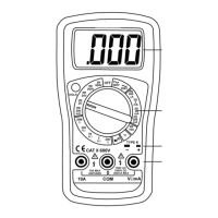
4. FRONT PANEL DESCRIPTION
Refer to Figure 1 to identify controls and terminals.
1. Display: Shows the reading value.
2. Rotary Switch: Turns ON and OFF the instrument
and select the function and the measurement range.
3. Temperature Socket: Used to measure temperature
with K Type termocouple.
4. Input Terminals: Terminals to connect the test leads.
COM - Common terminal, to connect the black test
lead, used in all functions, except hFE
measurement.
VΩmA - Positive terminal, to connect the red test
lead, used in AC and DC voltage, DC current until
200mA and resistance measurement and diode and
continuity test.
10A DC - Positive terminal, to connect the red test
lead, used to measure current between 200mA and
10A.
7
DIGITAL MULTIMETER
INSTRUCTION MANUAL
À(0.5%+2D)
À(0.8%+2D)
À(1.2%+10D)
À(1.5%+2D)
À(3.0%+5D)
À(1.0%+2D)
À(0.8%+4D)
À(0.8%+2D)
À(3.0%+3D)
T835