Do you have a question about the Top Vision Instore PRO 9 and is the answer not in the manual?
Basic precautions to follow before using an electrical unit.
Warning regarding opening the unit without qualified personnel.
Precautions for use, supervision, attachments, and handling damaged units.
Guidelines for cleaning the exterior and replacing parts by authorized personnel.
Defines the product's purpose for displaying eyewear and its commercial use.
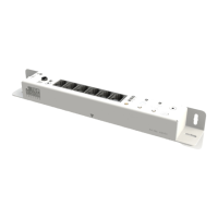
Details of the main receiver unit, including art code and dimensions.
Details of the receiver eye component, including art code and dimensions.
Specifications for the AC-DC adapter, including dimensions and cable length.
Details of the power cable, including art code and length.
Information on screws and spacers used for mounting.
Information about the remote control, including art code and dimensions.
Specification of drill bit and screwdriver needed.
Detailed technical specifications for the AC-DC adapter.
Detailed technical specifications for the receiver unit.
Information on using internal or external receiver eyes with placement options.
Specifies maximum distances for various cable connections.
Instructions for using an external receiver eye and drilling hole size.
Instructions for using an internal receiver eye and drilling hole size.
Shows horizontal, straight positioning on a panel with distances.
Shows horizontal, flat positioning on a panel with distances.
Shows vertical, straight positioning on a panel with distances.
Shows vertical, flat positioning on a panel with distances.
Shows horizontal, straight positioning on a wall with distances.
Shows horizontal, flat positioning on a wall with distances.
Shows vertical, straight positioning on a wall with distances.
Shows vertical, flat positioning on a wall with distances.
Illustrates drilling a 2.5mm predrill hole for mounting.
Shows mounting the receiver unit using screws and a screwdriver.
Illustrates drilling a 16mm hole for the external receiver eye.
Shows installing the external receiver eye with spacers.
Shows horizontal, flat positioning on a panel with distances.
Shows vertical, flat positioning on a panel with distances.
Illustrates pre-drilling with 2.5mm and drilling with 11.5mm holes.
Shows mounting the receiver unit using screws and a screwdriver.
Shows connecting RJ cables from columns to the receiver unit.
Shows connecting the jackplug to the IR receiver eye.
Shows connecting the DC cable to the power transformer.
Indicates the green LED signifies 'Power On'.
Procedure for adding IR codes to the receiver using the remote.
Procedure for deleting all programmed IR codes using the reset button.
Procedure for assigning the receiver to a specific group (1-3).
Setting the time interval for automatic column closing.
Details Top Vision product warranty period and coverage for defects.
Lists items not covered by the manufacturer's warranty.
Instructions for handling defects and voiding the warranty.
Contact details for Top Vision Group B.V. headquarters.
Provides contact information for various country distributors and offices.
| Brand | Top Vision Instore |
|---|---|
| Model | PRO 9 |
| Category | Receiver |
| Language | English |