V0
Peak discharge current /
time2
Series and parallel
connection
Max.4pcs battery parallel ,
series is not allowed.
2.3.1 First use
① When the battery leaves the factory, the button switch will be turned off and in the off state,
② Before the battery is used, the switch needs to be closed to the on state, and the LED indicator lights
up.
③ Before multiple batteries are connected in parallel, a multimeter shall be used to test the voltage at
both ends of the positive and negative poles of the battery to ensure that the voltage between the batteries
does not exceed 0.2V.
④ If the voltage between batteries exceeds 0.2V, each battery shall be fully charged separately and then
used in parallel.
2.3.3 Communication port
① 2 communication port, with CAN communication and RS485 communication;
② The battery can be upgraded through the communication port
③ It can communicate with other devices through the communication port, and the communication protocol
needs to be deployed before communication
2.3.4 ON or OFF
Topband R-B51100A battery has two switch. When the battery is transported or stored for a long time,
it can be turned off. This is a very low power consumption, ensuring that the battery can be stored for a long
time. At the same time, it is beneficial to improve the safety of the battery.
3. Installation
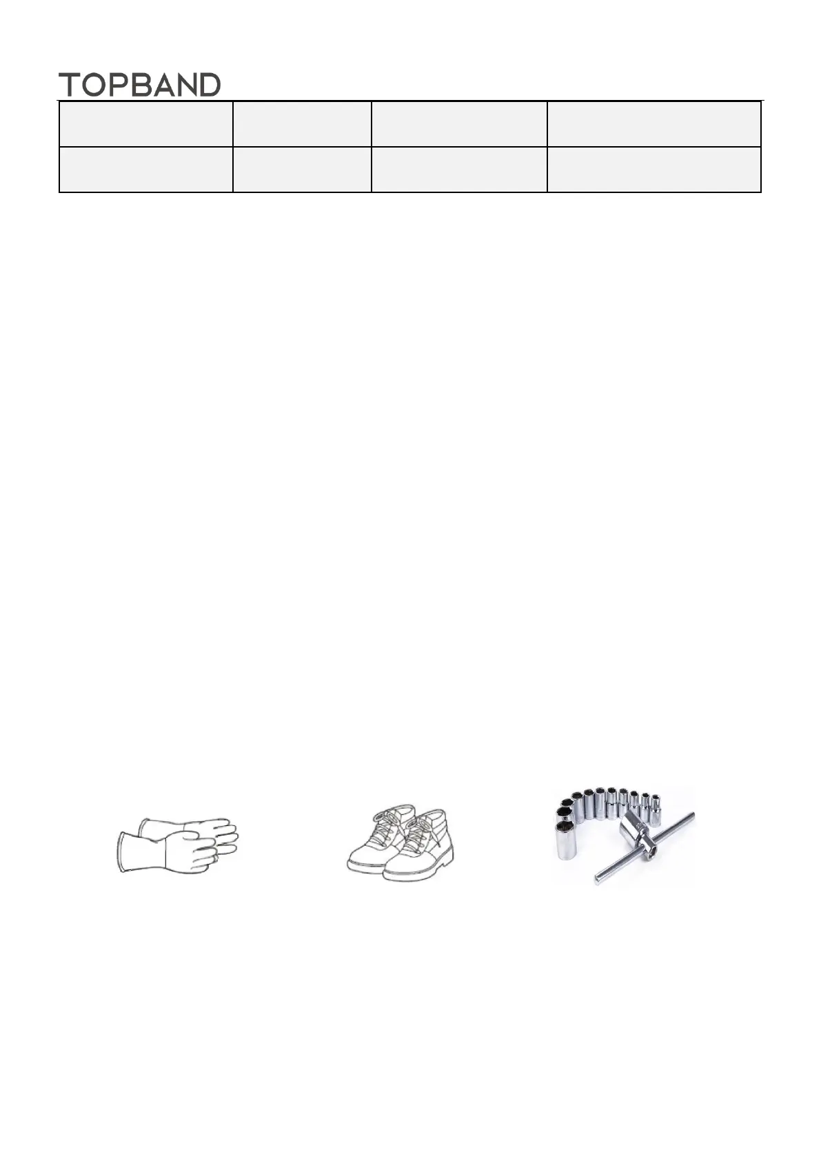
3.1 Tool And Equipment
Insulating Gloves Safety Shoes Spanner
3.2. Battery placement
Gently place the battery pack on the support surface with the front side up, do not place it on the side or
upside down, and do not place any covering above the pack. The schematic diagram of battery pack
placement is shown in Figure 3