3 short buzz Invalid input
1 long buzz Programming success
Continuous long buzz Restoring factory programming passwords
4. Definition of the output wires:
JP1 terminal
:
JP2 terminal
:
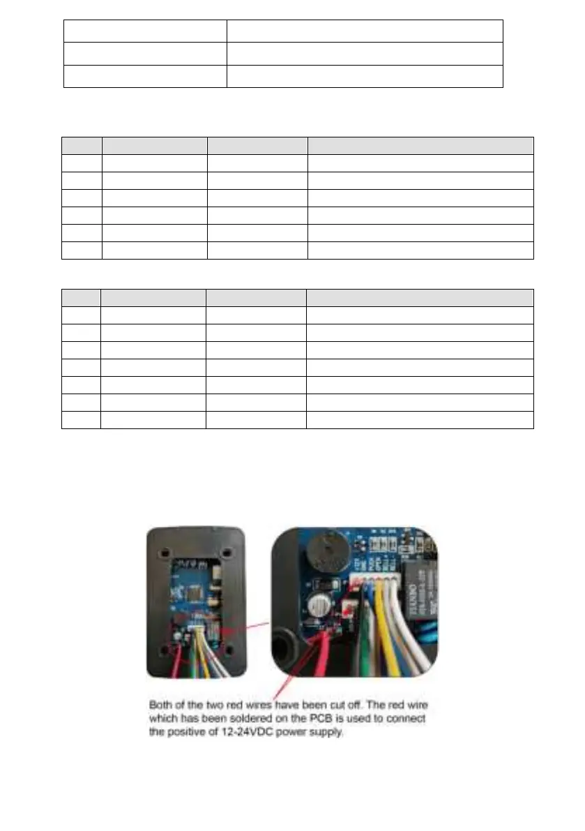
*NOTE: The red wire of the both 2 terminals has been cut off and it has been
soldered to the PCB of the keypad. Thus you can connect the 12-24VDC power
supply to the RED wire on the PCB and the BLACK wire of JP2 to power up the
keypad.
5. Wire connection of the keypad to the gate & door opener
NOTE: Below wiring diagram is a universal wiring diagram of the connection
between the keypad and the opener. You can refer to the user manual of the
This wire has been cut off
Power-(12-24VDC negative)
This wire has been cut off
Power-(12-24VDC negative)