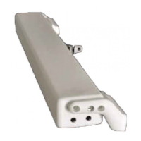
2) CONTROL AND FEEDING UNIT:
(RPR - 12V)
(RW) (RL)
3) SYNCHRONIZATION UNIT:
Fig.24-B Fig.34-B
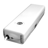
Microprocessor control units (e.g.: Mod. TF, EVP, etc.) controlling the single actuator
or more than one actuator simultaneously by means of one or more manual push-
buttons, an infrared remote control or a 433 Mhz radio control.
To these control units, it is possible to connect the rain sensors , the wind
sensor and the brightness sensor ;
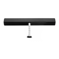
Microprocessor control unit (e.g.: Mod. USA2) controlling by means of a manual
push-button the simultaneous operation of 2 or 3 actuators installed on a single
window assuring the regular opening and closing movement.
A good method to perform the adjustment is to let the chain go back without load into the
actuator and, then, to measure the position of the chain ending with reference to the
external casings.
Then, tighten the window frame fixing screw and let the chain go back.
The adjustment is right, when with closed window the chain ending has the same
position detected during the test without load.
As given in (top hung windows) and in (bottom hung windows),
although the window is closed, part of the chain ending or of the chain itself has not
come back completely into the actuator casings causing the failed tripping of the related
limit switch related to the chain re-entering. In this case, the actuator motor remains
under conditions of maximum stress, until the electronic protection trips and the
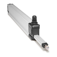
5.6- ADJUSTMENT OF THE WINDOW FRAME CLOSING (Fig.24-34)
THE CORRECT ADJUSTMENT OF THE WINDOW FRAME CLOSING ASSURES THE LIFE
AND THE TIGHTNESS OF THE SEALS, AS WELL AS THE GOOD OPERATION OF THE
ACTUATOR.
CONSIDERING THAT THIS ADDITIONAL SAFETY DEVICE HAS BEEN DEVELOPED IN
ORDER TO OFFER A RAPID SYSTEM TO DETECT ANY EVENTUAL ANOMALY IN THE
ASSEMBLY OF THE DEVICE, FOR A CORRECT INSTALLATION OF THE PRODUCT IT IS
COMPULSORY TO FOLLOW ALL THE ASSEMBLING PROCEDURES DESCRIBED IN THIS
MANUAL.
"BUZZER" is enabled.
This warning horn emits a continuous "beep" as long as the actuator is
connected to the power supply.
18
ACK4
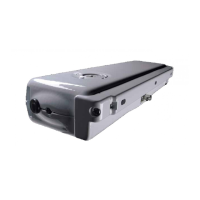
5- INSTALLATION
INSTALLATION AND USE ISTRUCTIONS
VER.1.0
REV.11.05