20
1
4
2
3
5
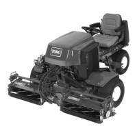
Figure 16
1. Counterbalance arm
2. Top capscrew
3. Bottom capscrew
4. Spring shackle
5. Clevis pin and cotter pin
6. Chain, clevis, and clevis
pin
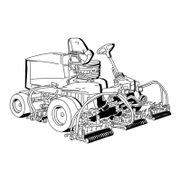
6. On the rear counterbalance arms, install the vinyl cover
over the spring before hooking the other end of the
spring into the spring shackle in the second hole from
the top (Fig. 17).
1 23
Figure 17
1. Rear counterbalance
spring
2. Vinyl cover
3. Spring shackle
7. Insert the breaker bar into the square hole in the
counterbalance arm and pivot the arm back to its
original position, aligning the mounting holes.
8. Secure the bottom of the counterbalance arm to the
frame with the capscrew and nut previously removed.
Tighten the top capscrew (Fig. 16).
9. To tension the counterbalance springs proceed as
follows:
A. Remove the cotter pin and clevis pin securing the
spring shackle to the counterbalance arm. Do not
remove the other clevis pin.
B. Move the shackle up or down on the counterbalance
arm until it is aligned with the desired hole on the
arm. Install the clevis pin and cotter pin.
Adding Rear Ballast
This unit complies with ANSl B71.4–1999 Standard and all
applicable European requirements when equipped with rear
ballast. Use the following chart to determine the weight or
combinations of weights needed.
Cutting Unit
Configuration
Weight Kits Required
Standard machine with
27” cutting units
(1) 83-9370
(2) 83-9390
Standard machine with
27” cutting units &
baskets
(1) 83-9370
(3) 83-9390
(2) 94-3698
Standard machine with
three wheel drive kit &
27” cutting units
(1) 83-9390,
(1) 83–9370
Standard machine with
three wheel drive kit, 27”
cutting units & baskets
(2) 83-9390
(2) 94-3698
(1) 83–9370
Standard machine with
32” cutting units
(3) 83-9390
(2) 94-3698
(1) 83–9370
Standard machine with
32” cutting units & three
wheel drive kit
(1) 83-9370
(2) 83-9390
(1) 94–3698
Note: All configurations require calcium chloride in the
rear tire. Tires should be filled to approximately 75%
capacity (valve level with valve at the top) (60 lb. fluid or
74 lb. tire and fluid).
Important If a puncture occurs in a tire with calcium
chloride, remove the unit from the turf area as quickly as
possible. To prevent possible damage to the turf,
immediately soak the affected area with water.
Either Type 1 (77%) or Type 2 (94%) commercial calcium
chloride flake may be used.
Plain water freezes solid at 32°F (0°C). The 3-1/2 lb.
(1.6 kg) calcium chloride to 1 gallon (3.8 l) of water
solution is slush free to –12°F (–24°C) and will freeze solid
at –52°F (–46°C). The 5 lb. (2.3 kg) per gallon (liter)
solution is slush free to –50° F (–45°C) and will freeze
solid at –62°F (–52°C).