15
2. Slide clevis pins through rod fittings and mounting
holes in idler brackets (from outside) (Fig. 9). Secure
with washers and hairpin cotters (Fig. 9).
m–2073
1
3
2
4
4
Figure 9
1. Control rod and fitting
2. 2 in. (51 mm)
3. Idler bracket
4. Clevis pin, washer and
hairpin cotter
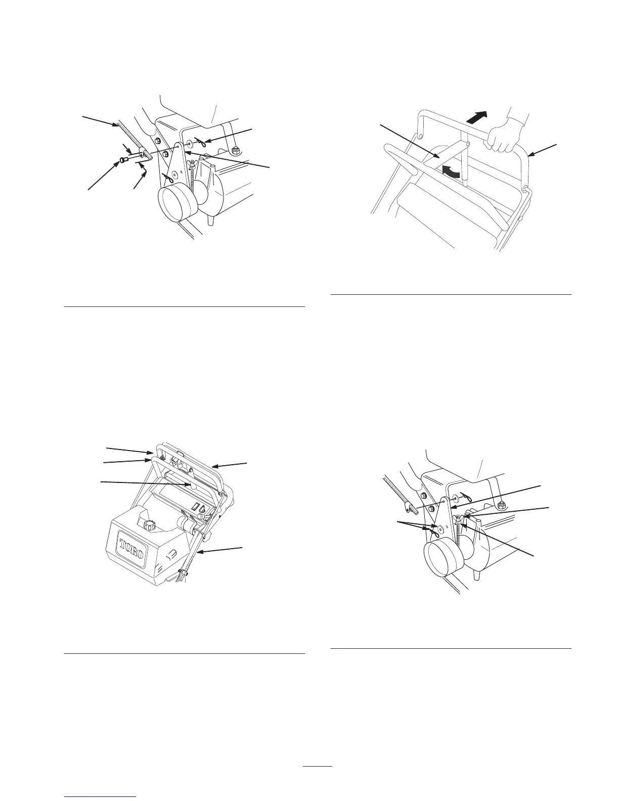
3. Check the gap between upper control bar and fixed bar
with wheel drive fully engaged. Gap should be
approximately 1 to 1-1/4 in. (25–32 mm) (Fig. 10).
Note: The upper control bar and fixed bar must be parallel
when in engaged, drive, relaxed and brake positions.
4. Check operation. If adjustment is required, remove
hairpin cotter securing rod to upper control bar. Thread
rod in or out of fitting for proper position and install
into upper control bar with hairpin cotter.
m–4183
1
2
3
4
5
Figure 10
1. Control rod
2. Fixed control bar
3. Parking brake lever
4. Upper control bar
5. 1 to 1–1/4 in. (25–32 mm)
5. Check parking brake adjustment. Brake rods should be
adjusted so parking brake lever is tight when swung
into position against the fixed bar while pulling back
on upper control bar (Fig. 11).
1
2
m–5233
Figure 11
1. Upper control bar 2. Parking brake lever
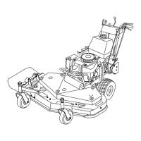
6. If brake adjustment is required, remove hairpin cotter
and washer securing brake rod fitting to idler bracket
(Fig. 12).
7. Adjust wing nut up or down on brake rod and secure
fitting to idler bracket (Fig. 12). Check adjustment and
readjust if necessary.
Note: Make sure brake rod is installed in front (F)
mounting hole in idler bracket.
8. Repeat procedure on opposite side if adjustment is
required to keep control bar and fixed bar.
1
2
3
4
m–2073
Figure 12
1. Idler bracket
2. Brake rod fitting
3. Hairpin cotter and washer
4. Wing nut