11
SET-UP INSTRUCTIONS
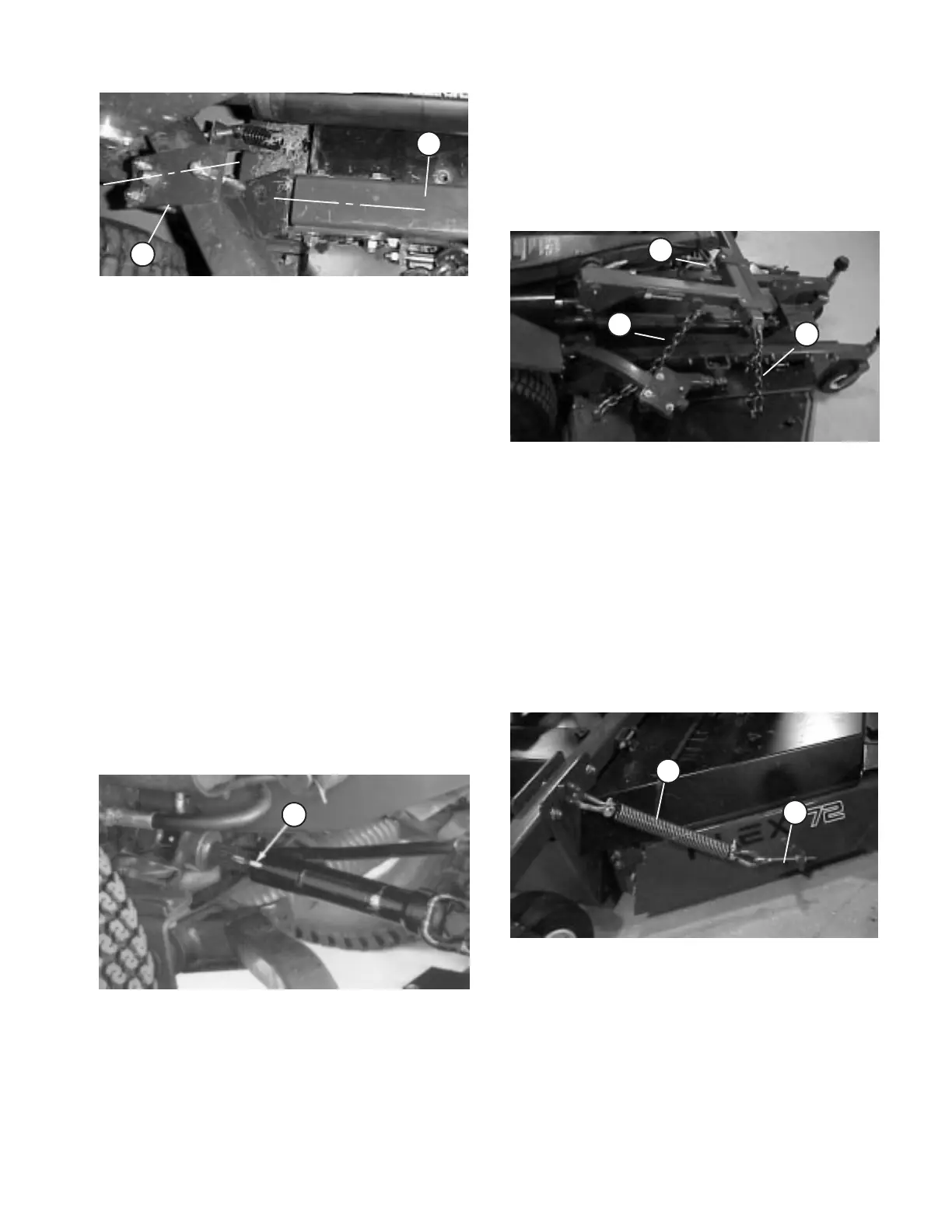
Figure 13
1. Lift bracket
2. Castor arm
1
2
2. Hook H.O.C. chain onto remaining U-bolt.
3. Thread a hex nut onto each end of U-bolt.
4. Loosely mount U-bolt and H.O.C. chain to rear lift
bracket (2) nuts and (2) flange nuts
5. Mount height-of-cut chain to 2" height-of-cut
hole with clevis pin and hair pin cotter.
6. Position rear castors in 2" height-of-cut.
7. Adjust nuts on U-bolt until rear of deck is parallel
to floor (Distance from floor to bottom rear edge of all
three deck chambers must be equal).
INSTALL DRIVE SHAFT TO TRACTION
UNIT
NOTE: To ease installation of PTO shaft, remove
right traction tire.
1. Slide smaller yoke end of drive shaft onto traction
unit PTO shaft while aligning mounting holes. Secure
with roll pin.
Figure 14
1. Drive shaft
1
INSTALL LIFT CHAINS (Fig. 15)
1. Connect lift chains to lift arm and cutting unit chain
brackets with (6) shackles, (3/8 x 1-1/2" lg.) shackle
pins and (1/8 x 3/4" lg.) cotter pins. To ensure cutting
unit lifts properly, secure chains to the following links
when connecting:
Front Left - 8th link
Front Right - 8th link
Rear - 14th link (All links)
Check operation to ensure all chains lift deck tight
against stops when lift arm is raised.
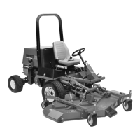
Figure 15
1. Front Left Lift Chain
2. Front Right Lift Chain
3. Rear Lift Chain
1
2
3
ADJUST COUNTER BALANCE SPRING
(Fig. 16)
1. Tighten nuts on adjusting rod until there is equal
weight on castor wheels of left and left center
chambers.
Figure 16
1. Counter balance spring
2. Adjusting rod
1
2
GREASE CUTTING UNIT
Before the cutting unit is operated, it must be greased
to ensure proper lubricating characteristics: refer to
Lubrication, page 13. Failure to properly grease the
cutting unit will result in premature failure of critical
parts.