13
BEFORE OPERATING
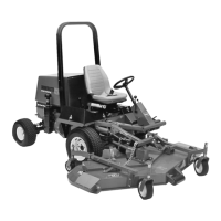
CHECK LUBRICANT IN GEAR BOX
The gear box in designed to operate on SAE 80-90 wt.
gear lube. Although the gear box is shipped with
lubricant from the factory, check the level before
operating the cutting unit.
1. Position the machine and cutting unit on a level
surface.
2. Remove check plug from side of gear box and
make sure lubricant is up to bottom of hole. If level of
lubricant is low, remove fill plug on top of gear case and
add enough lubricant to bring it up to bottom of hole in
side.
Figure 17
1. Filler Plug
2. Check Plug
3. Drain Plug
1
2
3
ADJUSTING HEIGHT - OF - CUT
The height-of-cut is adjustable from 1 to 4 inches in
1/4 inch increments.
1. Start the engine and raise the cutting unit so
height-of-cut can be changed. Stop engine after
cutting unit is raised.
FRONT CASTOR WHEELS
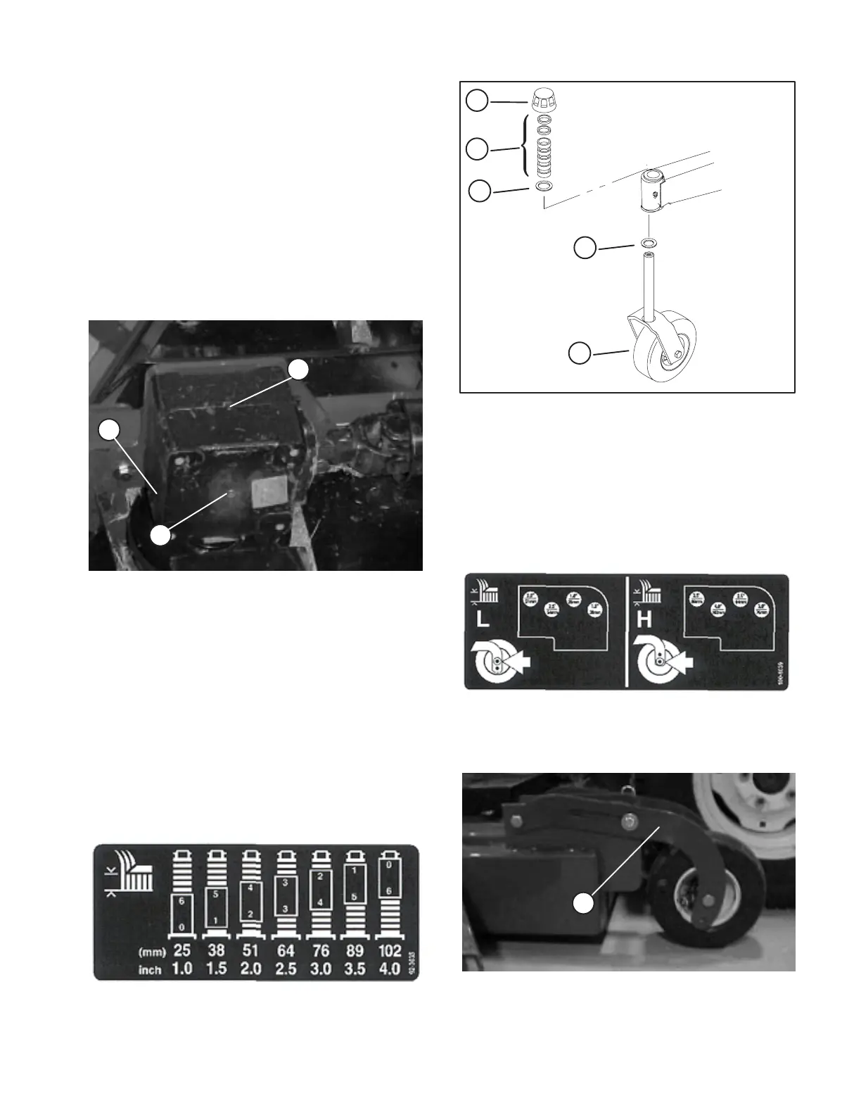
Figure 18
1. Remove H.O.C. cap from spindle shaft and slide
spindle out of front castor arm. Slide spacers onto
spindle shaft to get desired height-of-cut.
Figure 19
1. Front castor wheel
2. H.O.C. Cap
3. Spacer
4. Washer
2
3
4
4
1
2. Push castor spindle through front castor arm install
remaining spacers onto spindle and install HOC cap to
secure assembly.
REAR CASTOR WHEELS
Figure 20
1. Remove hairpin cotter and cotter pin securing rear
castor pivot arm to deck bracket.
Figure 21
1. Rear Castor Pivot
1
2. Align the pivot arm holes with selected
height-of-cut bracket holes in the deck frame, install
cotter pin and secure with hairpin cotter.