21
MAINTENANCE
1. Remove locknut from capscrew holding castor
wheel assembly between castor fork. Grasp castor
wheel and slide capscrew out of fork.
2. Pull spanner bushing out of wheel hub.
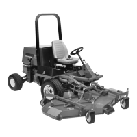
Figure 34
1. Castor wheel
2. Capscrew & Locknut
3. Bushing (2)
4. Spanner Bushing
5. Roller Bearing
6. Washer (2)
1
2
3
4
5
6
6
3. Remove bushing from wheel hub and allow
bearing to fall out. Remove bushing from opposite side
of wheel hub.
4. Check the bearing, spanner and inside of wheel
hub for wear. Replace defective parts.
5. To assemble the castor wheel, push bushing into
wheel hub. Slide bearing into wheel hub. Push other
bushing into open end of wheel hub to captivate the
bearing inside the wheel hub.
6. Carefully slide spanner through the bushings and
the wheel hub.
7. Install castor wheel assembly between castor fork
and secure in place with capscrew, washers and
locknut.
8. Lubricate castor wheel bearing through grease
fitting, using No. 2 general purpose lithium base
grease.
REPLACING GRASS DEFLECTOR (Fig. 35)
1. Position machine on a level surface, raise cutting
unit, engage parking brake, be sure traction pedal is in
neutral position, PTO lever in OFF position, shut engine
OFF and remove key from switch. Block cutting unit to
prevent it from falling accidentally.
2. Remove two capscrews, locknuts and springs
securing deflector mounts to pivot brackets.
3. To remove the pivot brackets, remove carriage
bolts and nuts.
4. Reinstall pivot brackets on top of discharge
opening with carriage bolts and nuts. Head of carriage
bolts must be on inside of cutting unit.
5. Position deflector mounts on pivot brackets and
secure parts together with capscrews, locknuts and
springs. Both locknuts must face each other. Tighten
locknuts until they are flush against deflector pivots.
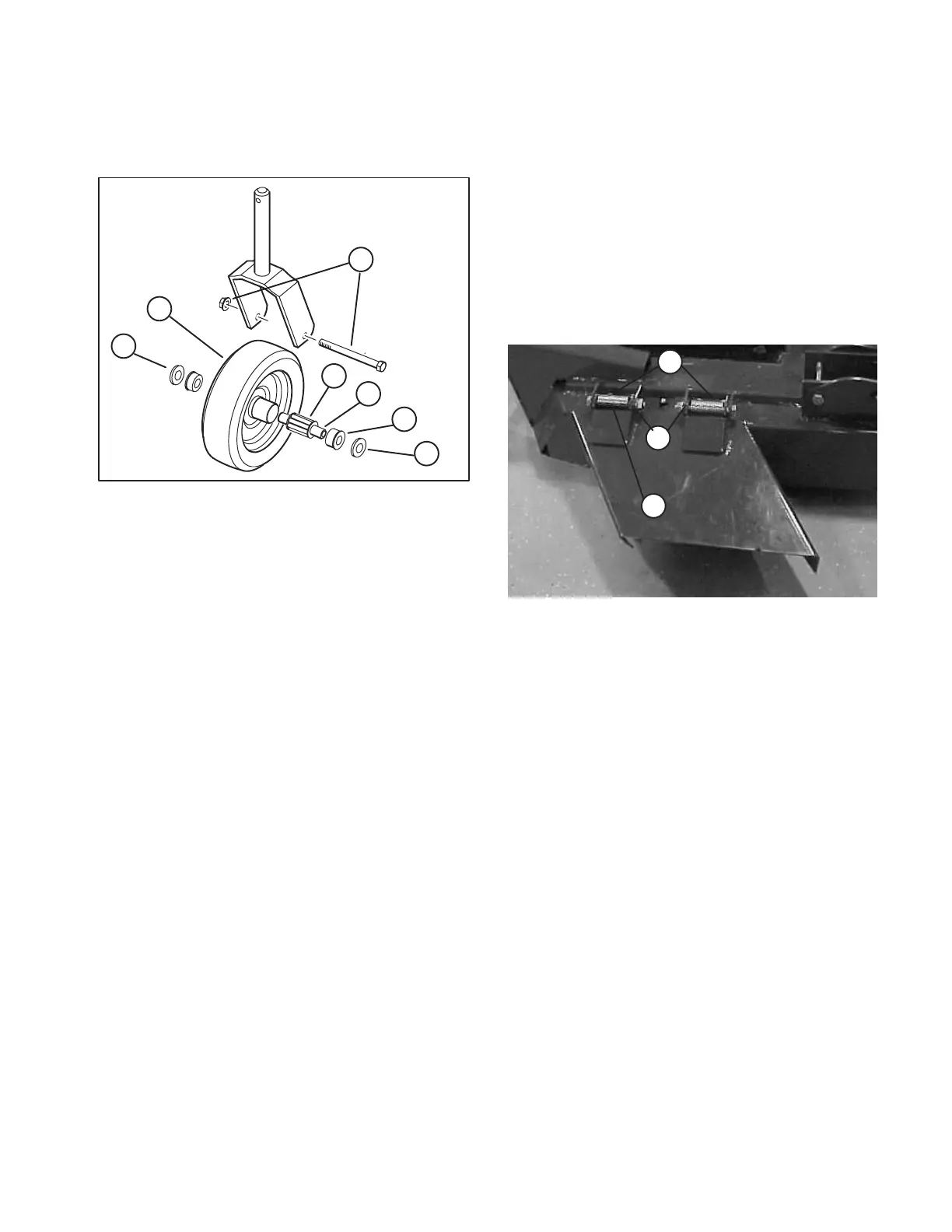
Figure 35
1. Deflector mounts
2. Pivot brackets
3. Pivot springs
3
2
1
6. Lift deflector and allow it to drop to check spring
tension. Deflector must be held firmly in full downward
position by spring tension. Correct if necessary.
REMOVING CUTTER BLADE (Fig. 36)
The blade must be replaced if a solid object is hit, the
blade is out-of-balance or if the blade is bent. Always
use genuine TORO replacement blades to be sure of
safety and optimum performance. Never use
replacement blades made by other manufacturers
because they could be dangerous.
1. Raise cutting unit to highest position, shut the
engine off and engage the parking brake. Block cutting
unit to prevent it from falling accidentally.
2. Grasp end of blade using a rag or thickly padded
glove. Remove blade bolt, lockwasher, anti-scalp cup
and blade from spindle shaft.
 Loading...