8
SET-UP INSTRUCTIONS
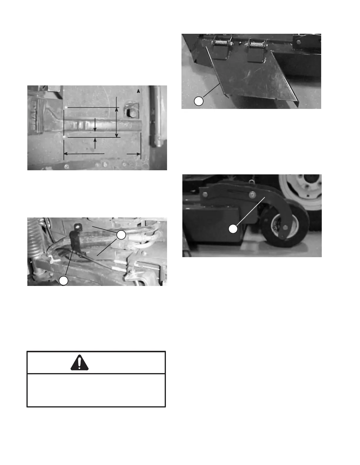
MOUNT HOSE CLAMP (Fig. 1 -2)
1. Using dimensions shown in figure 1, locate, mark
and drill (2) .280" dia. holes in traction unit platform.
Use caution when drilling as there are hoses and
cables under platform.
Figure 1
.75"
4.41"
12.75"
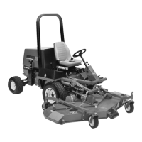
2. Secure hoses to under side of platform with clamp,
(2) brackets, capscrews and nuts. Position brackets to
fit contour of hoses and platform.
Figure 2
1
1. Clamp
2. Bracket (2)
2
GRASS DEFLECTOR (Fig. 3)
3. Remove shipping bands allowing deflector to be
lowered.
Defector is spring loaded in the down position
and will rotate downward, if not retrained,
when band is cut. If done improperly, personal
injury may occur.
WARNING
Figure 3
1. grass Deflector
1
MOUNT REAR CASTOR WHEELS (Fig. 4)
The rear castor wheels are shipped secured upside
down to deck brackets.
1. Remove capscrew and locknut securing front of
rear castor pivot to deck bracket.
Figure 4
1. Rear castor pivot arm
1
2. Turn pivot right side up and secure front of castor
pivot arm to front of deck bracket with capscrew and
locknut removed.
3. Align the pivot arm holes with selected
height-of-cut bracket holes in the deck frame, install
clevis pin and secure with hairpin cotter.
4. Repeat procedure on other castor wheel
assembly.
CONNECT RIGHT HAND PUSH ARM TO
CUTTING UNIT (Fig. 5- 6)
Note: Ball joints are shipped with traction unit.
1. Thread a jam nut fully onto ball joint.
2. Thread ball joint into push arm adapter until a
dimension of 2-3/8" from end of adapter to center of
ball joint is attained. Do not tighten jam nut.