25
MAINTENANCE
REPLACING BLADE DRIVE BELT
IMPORTANT: To replace the blade drive belt, the
rider may be tipped on its rear end. However, beĆ
fore the rider is tipped, drain all gasoline from
fuel tank and oil from crankcase. Also remove
battery so acid does not spill onto the rider.
1. Drain gasoline from fuel tank: refer to Draining
Gasoline From Fuel Tank, page 21.
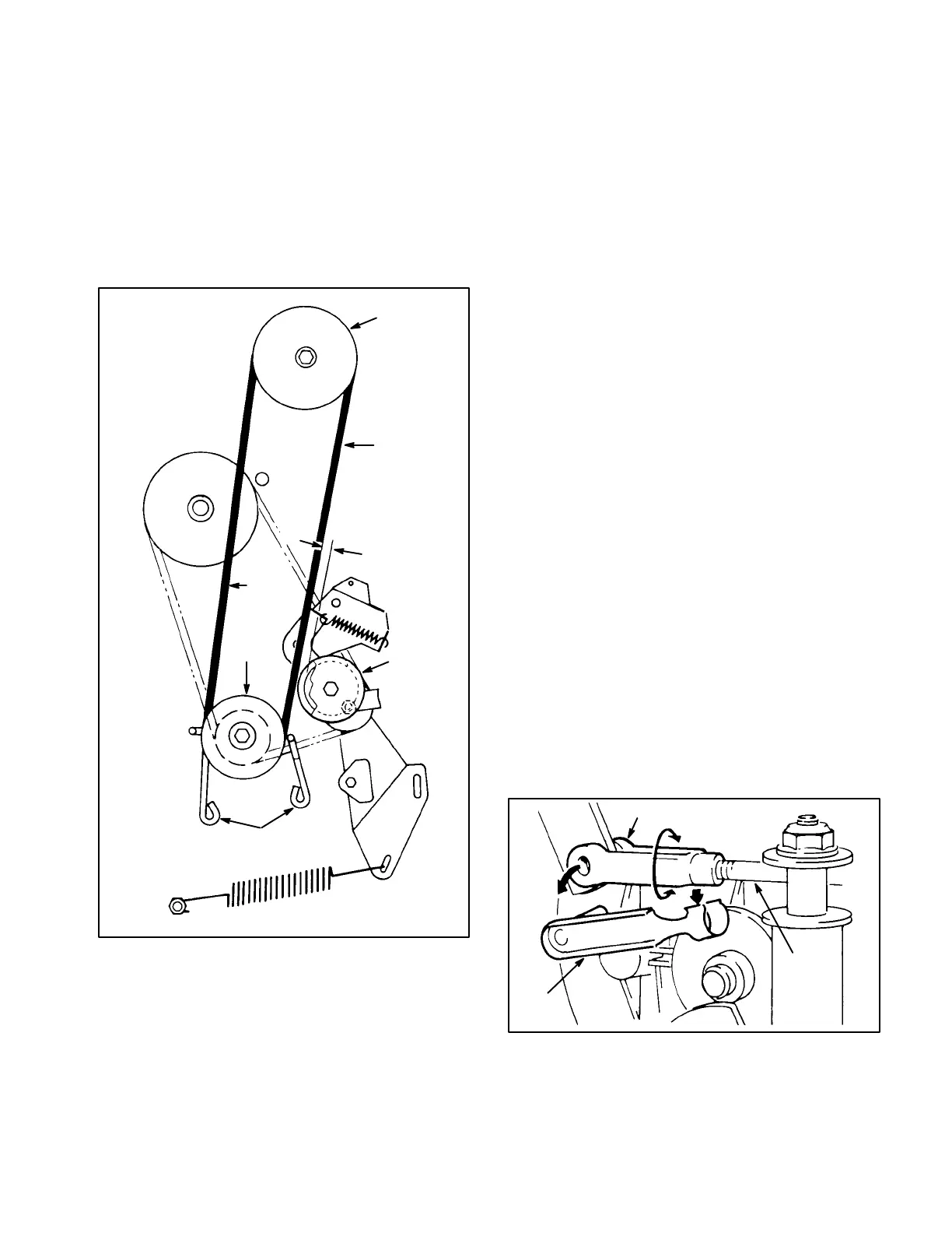
Figure 19
1. Blade drive belt
2. Engine pulley
3. Engine pulley belt guides
4. Mower housing pulley
5. Idler pulley
1587a
4
2
1/8 inch
1
(3 mm)
Push
out
here
3
5
2. Drain oil from crankcase: refer to Changing
Crankcase Oil, steps 1-6, page 20.
3. Remove battery from chassis: refer to Activating
and Charging Battery, page 11.
4. Shift transmission into 1st gear and engage the
parking brake. Tip rider onto its rear end.
5. Remove capscrews, retainers and locknuts seĆ
curing deck stops to each side of mower frame
(Fig. 18). Slide mower housing rearward to release
belt tension.
6. Move height-of-cut control to lowest position.
7. Loosen capscrews securing (2) engine pulley
belt guides and move guides away from pulley. ReĆ
move deck drive belt from engine pulley (Fig. 19).
8. Move blade control into ENGAGE detent so
brake is away from mower housing pulley.
9. Remove (2) screws securing belt guide to mower
housing and remove belt guide. Remove belt from
pulley.
10. Make sure blade control is in ENGAGE detent so
brake is away from mower housing pulley and install
new belt around pulley. Reinstall belt guide to mower
housing.
11. Route belt around engine pulley and reinstall belt
guides. Make sure belt guides are within 1/8" of
pulley or belt but not making contact.
12. Pushing out on belt (removing slack), as shown
in fig. 19, check clearance between outside of belt
and inside of idler pulley (Fig. 19). Clearance should
be approximately 1/8 inch (3mm).
13. If clearance between belt and pulley is correct,
proceed to step 16, otherwise proceed to next step
for adjustment procedure.
14. Locate deck engagement rod end on left side of
transmission (Fig. 20). Remove clevis pin retainer
and rotate clevis to lengthen or shorten rod until deĆ
sired clearance between belt and pulley is attained.
Figure 20
1. Deck engagement rod
2. Clevis pin retainer
3. Clevis
1591
3
1
2
15. Reconnect clevis and recheck adjustment.
16. Tip rider back to its normal position.
 Loading...