Maintenance
57
Replacing
the Deck Belt
Squealing when the belt is rotating, blades slipping
when cutting grass, frayed belt edges, burn marks and
cracks are signs of a worn deck belt. Replace the deck
belt if any of these conditions are evident.
1. Stop the engine, set the parking brake, remove
the key and disconnect the spark plug wire(s)
from the spark plug(s).
2. Remove the PTO drive belt. Refer to Replacing
the PTO Drive Belt, on page 57.
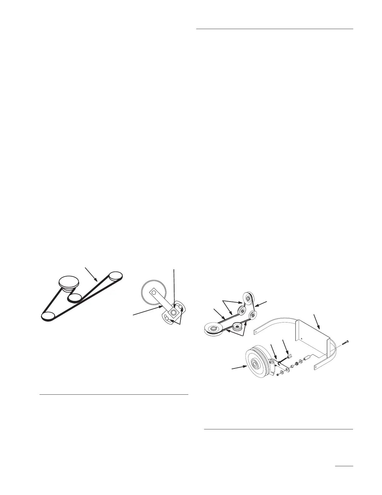
3. Loosen two nuts securing idler plate and move
the idler arm to relieve belt tension on the idler
pulley, then remove the worn deck belt (Fig. 48).
4. Install the new deck belt around the spindle
pulleys, belt guide, the idler pulley, and in the
lower groove of the center spindle pulley
(Fig. 48).
5. Using a socket and torque wrench, rotate the
idler adjusting nut until torque is 25–30 ft.–lb.
(34–41 Nm). Tighten two nuts.
2
1
3
4
M-4312
Figure 48
T
op V
iew
1. Deck
Belt
2.
Idler Arm
3.
Idler nuts
4.
Idler adjusting nut
6. Reinstall the PTO drive belt. Refer to Replacing
the PTO Drive Belt, page 57.
Replacing
the PT
O Drive Belt
Squealing when the belt is rotating, blades slipping
when cutting grass, frayed belt edges, burn marks and
cracks are signs of a worn drive belt. Replace the
PTO drive belt if any of these conditions are evident.
1. Stop the engine, set the parking brake, remove
the key and disconnect the spark plug wire(s)
from the spark plug(s).
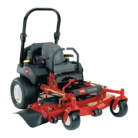
2. Remove the clutch retaining strap from machine
frame and unplug clutch terminal from wire
harness (Fig. 49).
3. Remove PTO drive belt from rear idler arm and
front idler pulley assembly. Remove the PTO
drive belt (Fig. 49).
4. Place new drive belt over clutch, around rear
idler pulley, installed into rear idler arm
assembly, installed into front idler pulley
assembly and onto top center pulley (Fig. 49).
IMPORTANT: Check the amount of twist in
belt between pulleys. Make sure it is only
what is specified in figure 49.
5. Install clutch retaining strap and plug clutch
terminal into main wire harness (Fig. 49).
1
4
m–4451
M-4373
3
2
5
7
6
6
Figure 49
1. Clutch
2. Clutch
retaining strap
3.
clutch T
erminal
4. PT
O belt
5.
Machine Frame
6.
1/4“ Belt T
wist
7.
1/8” Belt T
wist