CONTROLS
4-25Toro GrandStand Service Manual
4
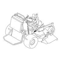
3. Position the control fork on the shoulder hub with
the forked end straddling the pump control arm (Fig.
0724).
5. Loosely install the switch stop arm and nut securing
the control fork and shoulder hub assembly to the
linkage mount (Fig. 0726).
Note: This will be tightened later in this procedure.
Fig. 0724 IMG-1050a
4. Install the bolt with washer through the center of the
shoulder hub (Fig. 0725).
Fig. 0725 IMG-1044a
Fig. 0726 IMG-1043a
Shifter Link and Roller Congurations (Fig. 0727):
D. 2009: Serial range 290000001-290000210;
3 rollers, all thin and same size
E. 2009: Serial range 290000211-290999999;
3 rollers, large center roller
F. 2010: Serial range 310000001-310999999;
3 rollers, all large and same size
Fig. 0727 IMG-0941a
A
B
C

 Loading...


