ENGINE
5-4 Toro GrandStand Service Manual
5
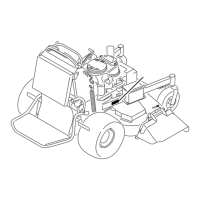
14. Remove the four nuts, two mounting guard brackets,
and four carriage bolts retaining the mufer guard
assembly to the front frame (Fig. 0847).
Note: 60” models have a guard panel, not the two
guard mounting brackets
17. Loosen the screw on the throttle cable clamp and
remove the throttle cable from the engine panel
control (Fig. 0850).
16. Loosen the screw on the choke cable clamp and
remove the choke cable from the engine panel
control (Fig. 0849).
Fig. 0847 IMG-0475a
15. Remove the mufer guard assembly (Fig. 0848).
Fig. 0848 IMG-0481a
Fig. 0849 IMG-0483a
Fig. 0850 IMG-0484a

 Loading...


