HYDRAULIC DRIVE SYSTEM
6-43Toro GrandStand Service Manual
6
33. Remove the spring clip from the drive linkage mount
(Fig. 1057).
Fig. 1057 IMG-9350a
A. Lift bar B. Brake rod
34. Remove the 2 traction control cables from the drive
linkage mount slots (Fig. 1058).
Fig. 1058 IMG-9351a
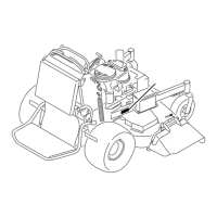
35. Lift the tower assembly up off the frame and lay it
back as shown, taking care that the lift bar is routed
out from under the right hand lift cylinder and the
brake rod is routed out from under the control panel
(Fig. 1059).
Fig. 1059 IMG-9352a
A
B
36. Remove the cable tie securing the wire harness and
2 low pressure hydraulic hoses (Fig. 1060).
Fig. 1060 IMG-9354a
 Loading...


