17
OPERATING INSTRUCTIONS
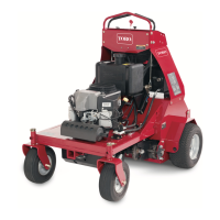
1. Coring depth adjustment screw
2. Adjusting bracket
3. Jam nut
Figure 14
1
2
3
11/16"
CHECK FRAME HEIGHT
1. Position machine on a level surface.
2. Check tire pressure. Tire pressure should
be10 psi. Make sure all tires are equal pressure.
3. Slide short end of frame height gauge under front
axle to verify height. Gauge should contact axle when
on floor. Check both sides (Fig. 15).
1. Front axle
2. Height gauge
Figure 15
1
2
4. Increase or decrease tire pressures to attain
required height.
5. Repeat procedure using long end of height gauge
on each rear wheel spindle (Fig. 16).
6. Regulate tire pressure as required. Minimum tire
pressure is 6 psi.
1. Rear wheel spindle
2. Height gauge
Figure 16
1
2
OPERATING PROCEDURE
1. Make sure wires are installed on spark plugs.
2. Start the engine: refer to Starting/Stopping
instructions.
3. Make sure coring head is in the up position.
4. Squeeze left interlock lever against handle.
5. Move shift lever to L" (low) for Coring or H" (high)
for Transport.
Note: If resistance is encountered during gear
selection, jog the clutch handle until the gears align. Do
not shift gears while machine is moving. DO NOT
FORCE SHIFT LEVER AS DAMAGE WILL OCCUR.
6. Move traction drive lever to engage position.
7. To engage and lower coring head, move coring
head lever to down position and hold until coring head
is completely lowered.
CHECK INTERLOCK SYSTEM
The purpose of the safety interlock system is to prevent
the engine from cranking or starting unless the traction
drive lever is disengaged and the coring head is raised.
It also interrupts engine operation if a handle mounted
interlock lever is not activated.
To check interlock system:
1. Position machine on a flat, open area. Start the
engine: refer to Starting and Stopping instructions.
2. Check traction switch (Fig. 17) with a continuity
tester or ohm meter and replace if damaged. The
switch must be closed when the gear shift lever is in a
gear. The switch must open when shifting between
Neutral, First, and Second gears.
3. To adjust switch, loosen mounting screws and
reposition switch as required.

 Loading...