EasyManua.ls Logo

toscano TPM6-DRAIN User Manual

toscano TPM6-DRAIN
4 pages
To Next Page IconTo Next Page
Page #1 background imageLoading...
Page #1 background image
ed.1
TPM6-DRAIN
quick guide
overview
Power supply
230/400Vac - 50/60Hz
Pilot lights (LED) Pump running, High level alarm, Maximum current, Minimum current, Timer, Pump alarm
Protections Overload, Underload, Phase loss, Jammed impeller
Displayed information (4-digit LED display) Pump consumption, Maximum current, Minimum current, Timer, Alarms, Settings
Pump output
12A maximum (up to 40A with auxiliary contactor)
High level alarm output
5A maximum
Pump alarm output
5A maximum
Maximum current setting Auto - 0.6...40A (trip in 7 s)
Minimum current setting OFF - 0.5...40A (trip in 4 s with 20 s starting delay)
Timed dose setting OFF - 3 min...24 h
Limited run time setting 30 s...30 min
Maximum terminal cross-section
4mm² (power) / 2,5mm² (control)
specifications
connection diagrams
A B C D
4
2
1
3
E F G
5
6
Terminals
A. Power supply 230/400V input.
B. Pump supply output.
C. High level alarm output.
D. Pump alarm output.
E. 90dB alarm buzzer output.
F. High level alarm float switch
input.
G. Level control input (probes /
float switches).
H. Current transformer input.
Pilot lights
1. Pump running.
2. High level alarm.
3. Overload setting.
4. Underload setting.
5. Timer setting.
6. Pump alarm.
H
Pump
12A
max.
dimensions
single-phase basic diagram
(three-phase pump by contactor)
phase loss
active only
Imin > OFF
Pump
12A
max.
Pump
12A
max.
Pump
12A
max.
Question and Answer IconNeed help?

Do you have a question about the toscano TPM6-DRAIN and is the answer not in the manual?

toscano TPM6-DRAIN Specifications

General IconGeneral
Brandtoscano
ModelTPM6-DRAIN
CategoryTouch terminals
LanguageEnglish

Summary

quick guide

overview

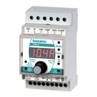
Details the TPM6-DRAIN unit, its terminals, pilot lights, and dimensions for identification and basic understanding.

specifications

Outlines technical parameters including power supply, pilot lights, protections, display information, outputs, and current settings.

connection diagrams

Illustrates various wiring configurations for single-phase and three-phase pump connections, including float switches.

current set-up

option A: automatic current set-up

Explains the procedure for automatically configuring the current limits (Imax and Imin) for pump protection.

option B: manual current set-up

Details the steps for manually setting overload (Imax) and underload (Imin) current thresholds.

operator control

manual mode

Covers manual operations such as stopping the pump, activating manual mode, and initiating pump start.

status

Describes how to interpret unit status indicators, including OFF/ON states and various operational values.

reset (alarms, dose timer and run timer)

Provides instructions for resetting alarms, timed dose, and run timers for operational management.

additional protections

built-in jammed impeller protection

Explains the function and operation of the jammed impeller protection feature.

high level alarm float switch

Details the wiring and activation of a float switch for high-level alarm detection.

level control - 230V pump with built-in float

basic control

Illustrates basic level control operation for a 230V pump using a built-in float switch.

pump pilot with built-in float

Shows the wiring and operation for a pump pilot system utilizing a built-in float switch.

timed dose

timed dose (Imin = OFF / Ø = d3'...d24h)

Explains the timed dose function, allowing setting pump operation duration from 3 minutes to 24 hours.

limited run time

limited run time (Imin = OFF / Ø = r30"...r30')

Describes the limited run time feature, setting maximum pump operation periods from 30 seconds to 30 minutes.

level control - multiple float switches

basic control

Demonstrates basic level control configurations using multiple float switches in various tank level scenarios.

timed dose

Illustrates timed dose operation with multiple float switches, controlling pump cycles based on time and level.

limited run time

Shows limited run time functionality with multiple float switches, managing pump operation duration and preventing continuous runs.

extras

optional battery charger

Mentions the availability of an optional battery charger accessory for the unit.

conductive probes

Explains the connection and usage of conductive probes for level detection in conductive liquids.