EasyManua.ls Logo

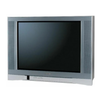
Toshiba 24AF41 User Manual

Toshiba 24AF41
37 pages
To Next Page IconTo Next Page
Page #1 background imageLoading...
Page #1 background image
TOSHIBA
FILE NO.050-200103
SERVICE MANUAL
COLOR TELEVISION
24AF41
DOCUMENT CREATED IN JAPAN, DEC., 2001
Question and Answer IconNeed help?

Do you have a question about the Toshiba 24AF41 and is the answer not in the manual?

Toshiba 24AF41 Specifications

General IconGeneral
BrandToshiba
Model24AF41
CategoryTV
LanguageEnglish

Summary

Servicing Notices and Safety Precautions

General Servicing Precautions

Key safety notices including electric shock, part usage, and post-service checks.

How to Order Parts

Include model number, version letter, part number, and description when ordering parts.

General Specifications

General Specifications (Continued)

Disassembly Instructions

Anode Cap Removal and Installation

Procedure for safely removing and reinstalling the anode cap.

Service Mode Operations

Service Mode List and Access

Lists service modes, their functions, and how to access them.

Using Service Mode Functions

Procedures for checking usage hours and replacing memory IC.

Electrical Adjustments

Pre-Adjustment Procedures and Tools

Safety notes, required tools, and OSD adjustment setup.

Basic Adjustments

Covers constant voltage, RF AGC, cut off, white balance, focus, and H. POSI.

Electrical Adjustments (Continued)

Picture Geometry Adjustments

Adjustments for horizontal/vertical size, position, parabola, trapezium, and corners.

Signal Separation and Color Adjustments

Adjusts stereo separation, brightness, uni-color, sub tint, and sub color.

OSD and Level Adjustments

Adjusts OSD horizontal position and audio/video signal level.

Purity and Convergence Adjustments

Preparation and Static Adjustments

Warm-up, demagnetization, and static convergence setup.

Purity and Dynamic Adjustments

Adjusts purity, static convergence, and dynamic convergence.

Component Location Guide

PCB Component Layouts

Diagrams showing component placement on Main and CRT PCBs.

Micon/Tuner Schematic Diagram

Chroma/IF Schematic Diagram

Deflection Schematic Diagram

Power Schematic Diagram

Sound Schematic Diagram

AV Schematic Diagram

Comb Filter Schematic Diagram

CRT/SVM Schematic Diagram

Mechanical Exploded View

Exploded View Diagram of Parts

Visual representation of all mechanical parts and their assembly order.

Mechanical Replacement Parts List

Mechanical Parts Inventory

Detailed list of mechanical parts with location, TSB P/N, and description.

Electrical Replacement Parts List - Resistors, Capacitors, Diodes

Resistor Specifications

List of resistors with location, TSB P/N, type, and value.

Capacitor Specifications

List of capacitors with location, TSB P/N, type, and value.

Diode Specifications

List of diodes with location, TSB P/N, type, and model.
Related product manuals