4-48 420 Series
6. Disconnect the flexible cable from CN-IN on the LCD module.
7. Remove the shielded tape securing the display cables to the LCD cover.
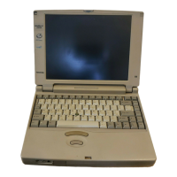
Figure 4-48 Removing the LCD module (DSTN)
Installing the LCD Module
To install the LCD module, follow the steps below and refer to Figures 4-48 and 4-47.
1. Secure the display cable to the LCD cover with shielded tape.
2. Connect the flexible cable to CN IN on the LCD module.
3. Connect the display cables to PJ2, PJ3, and PJ4 on the flexible cable and
connect the flexible cable to the display module.
4. Carefully rotate the LCD module into the LCD cover.
NOTE: Support the back of the display with your hand when you secure the
screws.
5. Secure four M2.5x6 screws on the LCD module. Make sure the ground cable is
secured at the lower left corner.
6. Install the FL inverter board, display mask, optional memory module, optional PC
card, and battery pack as described in Sections 4.18, 4.16, 4.4, 4.3, and 4.2.
 Loading...