EasyManua.ls Logo

Toshiba 420CDT User Manual

Toshiba 420CDT
201 pages
To Next Page IconTo Next Page
Page #1 background imageLoading...
Page #1 background image
420 Series 1-1
1.1 Features
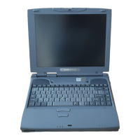
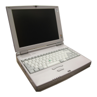
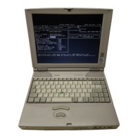
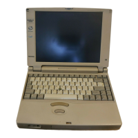
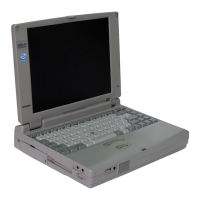
The 420CDT/420CDS (420 Series) is one of the lightest and most advanced portable comput-
ers available. Utilizing advanced technology and high-speed components, the 420 series
offers multimedia functions, excellent display legibility, battery operation, and IBM PC/AT
compatibility. The 420 series system unit consists of the following features:
Microprocessor
An Intel Pentium processor with Voltage Reduction Technology (VRT) that operates
at 100 MHz and 3.3/2.9 volts.
Disk storage
The 420CDT has an internal 1.3 billion byte (1.26 GB) or 810 million byte (770 MB)
Hard Disk Drive (HDD). The 420CDS has an internal 810 million byte HDD. A 3.5-
inch Floppy Disk Drive (FDD) supports 2HD (1.44 MB) floppy disks and 2DD (720
KB) floppy disks. The FDD can also be installed in an attachment for connection as an
external device.
CD-ROM Drive
A full-size, six-speed CD-ROM drive module can be installed instead of the FDD
module. The CD-ROM drive contains an ATAPI (AT attachment packet interface)
interface controller, and supports the following formats: audio CD, photo CD, CD-
plus, and ISO 9660.
Memory
Standard with 8 MB of CMOS RAM. This includes 640 KB of conventional memory
and 7360 KB of extended memory, which can be utilized as expanded memory com-
patible with the Lotus/Intel/Microsoft Expanded Memory Specification (LIM-EMS).
Display
The 420CDT has an 11.3-inch, Thin Film Transistor (TFT) color LCD with 800 x 600
pixels. The 420CDS has an 11.3-inch Dual-scan Supertwist Nematic (DSTN) color
LCD with 800 x 600 pixels. The built-in display controller supports 800 x 600 resolu-
tion with 16M colors capability and up to 1280 x 1024 resolution with 256 colors on
an external CRT.
Keyboard
An-easy-to-use 82/84-key keyboard provides a numeric keypad overlay for fast nu-
meric data entry or for cursor and page control. The keyboard supports software that
uses a 101- or 102-key enhanced keyboard.
Question and Answer IconNeed help?

Do you have a question about the Toshiba 420CDT and is the answer not in the manual?

Toshiba 420CDT Specifications

General IconGeneral
BrandToshiba
Model420CDT
CategoryLaptop
LanguageEnglish

Summary

1.1 Features

1.3 3.5-inch Floppy Disk Drive

1.4 2.5-inch Hard Disk Drive (HDD)

1.5 Keyboard

1.6 CD-ROM Drive

1.7 DSTN Color LCD (420CDS)

DSTN Color LCD Module

Backlit DSTN color LCD with 800x600 pixels, built-in controller for VGA/SVGA.

1.8 TFT Color LCD (420CDT)

LCD Module

Backlit TFT color LCD with 800x600 pixels, built-in controller for VGA/SVGA.

1.9 Power Supply

1.10 Batteries

Main Battery

Primary power source when AC cord is detached; recharges backup battery.

Backup Battery

Maintains data for AutoResume; powered by AC, main battery, or backup battery.

RTC Battery

Powers current date, time, and setup info when computer is off.

2.1 Troubleshooting

Field Replaceable Units (FRUs)

Lists components identified as Field Replaceable Units for troubleshooting purposes.

Troubleshooting Tools

Lists necessary tools like diagnostic disks, drivers, and hardware for troubleshooting procedures.

2.2 Troubleshooting Flowchart

2.3 Power Supply Troubleshooting

AC IN Icon Check

Procedure to check the AC IN icon status for power connection and supply issues.

Battery Icon Check

Procedure to check the Battery icon status for charging and battery pack issues.

2.4 System Board and Sound Board Troubleshooting

Message Check

Procedure to check system messages for errors related to RTC memory and configuration.

2.5 Floppy Disk Drive Troubleshooting

FDD Head Cleaning Check

Procedure for cleaning FDD heads using a diagnostic program and cleaning kit.

2.6 Hard Disk Drive Troubleshooting

Partition Check

Procedure to verify hard disk partition status using FDISK commands.

2.7 Keyboard Troubleshooting

Diagnostic Test Execution

Procedure to execute the keyboard test within the diagnostic program.

2.8 Display and VGA Board Troubleshooting

External CRT Check

Procedure to test the external CRT connection to diagnose internal LCD issues.

2.9 CD-ROM Drive Troubleshooting

CD Cleaning Check

Procedure for cleaning the CD-ROM laser pickup lens with a lens cleaner.

3.1 The Diagnostic Test

3.2 Executing the Diagnostic Test

4.1 General

Safety Precautions

Provides essential safety guidelines for disassembly and handling, including electrical and physical hazards.

Before You Begin Disassembly

Outlines procedures and environment checks before starting computer disassembly.

Disassembly/Assembly Procedures

Details cable connector types and general points for reassembling computer components.

Tools and Equipment

Lists necessary tools like screwdrivers, tweezers, ESD mats, and wrist straps for disassembly.

4.2 Battery Pack

Removing and Installing Battery Pack

Step-by-step instructions for removing and installing the battery pack.

4.3 Optional PC Card

Removing and Installing PC Card

Instructions for removing and installing an optional PC card, including eject button use.

4.4 Optional Memory Module

Removing and Installing Memory Module

Instructions for removing and installing an optional memory module, involving screws and connectors.

4.5 Floppy Disk Drive (FDD)

Removing and Installing FDD

Step-by-step guide for removing and installing the internal FDD, involving release lever and screws.

4.6 CD-ROM Drive

Removing and Installing CD-ROM Drive

Instructions for removing and installing the CD-ROM drive, using release lever and screws.

4.7 Hard Disk Drive (HDD)

Removing and Installing HDD

Instructions for removing and installing the HDD, involving frame brace and screws.

4.8 Keyboard

Removing and Installing Keyboard

Instructions for removing and installing the keyboard by releasing latches and disconnecting cable.

4.9 Sub-Battery and VGA Board

Removing and Installing Sub-Battery/VGA Board

Instructions for removing and installing sub-battery and VGA board, including cable connections.
4.10 RTC Battery and Top Cover with Display Assembly

4.11 Sound Board and Membrane Switch

4.12 Speaker

4.13 AC PS Unit

4.14 Infrared Board

4.15 System Board and Fan

4.16 Display Mask

4.17 Fluorescent Lamp (FL) Inverter Board (TFT model)

4.18 Fluorescent Lamp (FL) Inverter Board (DSTN model)

4.19 Liquid Crystal Display (LCD) Module (TFT model)

4.20 Liquid Crystal Display (LCD) Module (DSTN model)

4.21 FL (TFT model)

4.22 FL (DSTN model)

4.23 Microphone

Related product manuals