EasyManua.ls Logo

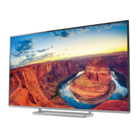
Toshiba 50L4333D User Manual

Toshiba 50L4333D
113 pages
To Next Page IconTo Next Page
Page #1 background imageLoading...
Page #1 background image
SERVICE MANUAL
LCD Color Television
50L4333D(G), (F)
50L4331D(G)
50L4337D(G), (F)
REVISED:01
Question and Answer IconNeed help?

Do you have a question about the Toshiba 50L4333D and is the answer not in the manual?

Toshiba 50L4333D Specifications

General IconGeneral
Screen Size50 inches
Display TypeLCD
HDMI Ports3
USB Ports2
Refresh Rate50 Hz
BacklightLED
Built-in Wi-FiNo
Smart TVYes
Resolution1920 x 1080 (Full HD)

Summary

Revision History

Important Notice

Green Product Procurement

Lead-Free Solder

Safety Instructions

Safety Precaution

Necessary precautions to be observed before servicing the chassis.

Service Mode

Entering Service Mode

Step-by-step instructions to access the service mode.

Key Function in Service Mode

Explains remote control button functions within service mode.

Test Signal Selection

How to cycle through built-in test patterns on screen.

Adjusting Items in Service Mode

Lists adjustable items with their descriptions for service mode.

LED Indications for Service

Hotel Mode

Entering Hotel Mode Menu

Operation to display the hotel mode settings menu.

Operating Hotel Mode Menu

How to enable and adjust settings within hotel mode.

Hotel Mode Settings

Control Panel Settings

Options for controlling panel button access in hotel mode.

Remote Control Settings

Controls enabling/disabling remote control functions.

Max Volume Setting

Limits the maximum volume level that can be set.

Change POS/VIDEO Setting

Configures default channel or input upon power on.

Hotel Clone

Copying Settings From TV To USB Drive

Procedure to save TV settings to a USB drive.

Copying Settings From USB Drive to TV

Procedure to load settings from USB drive to the TV.

Component Interconnection Diagram

Exploded View

Safety Precaution (Parts)

Critical parts identified by mark for safety.

Panel Identification

Main Board Exchange

Updating Software and Model Setting

Procedures for updating application SW and model settings.

About the Main Board

Peripheral Interface Circuits

GPIO Interface

General Purpose Input/Output pin configurations.

I2C Interface

Inter-Integrated Circuit communication interface.

Peripheral Circuits

Boot Configuration

Configuration related to boot process.

Reset Circuit

Details on the reset mechanism and related components.

DDR3 SDRAM A

DDR3 A Resistors

DDR3 SDRAM B

DDR3 B Resistors

DDR3 SDRAM Power

SPI Flash

EMMC

RJ45 Connector

USB Connector

Audio Line Driver

Headphone Amplifier

Audio D-AMP (Main)

Euro SCART Connector

DSUB15P PC Input

Euro Component Input

Optical HP/Fix Output

Euro SCART Output

AV Input 1

DSUB PC EDID

HDMI Connector

Backlight Control

T-CON Power Supply

3D Glasses Interface

Demodulator DVB-S2/S

HDMI HPD(1)

HDMI HPD(2)

HDMI DDC

HDMI HDCP Key ROM

MHL Bridge 1/2

MHL Power Supply

MHL VBUS Power

HDMI CBUS HPD

Keypad Interface

Tuner Circuitry

Tuner IF and AGC

Demodulator T2/ISDBT

DiSEqC and LNB Power

CI Connector

CI BUS 1

CI BUS 3

CI BUS 2

CI Control

CI TS Input/Output

Power 3.3V Standby

Power 1.15V (Core)

Power 3.3V Supply

Power 6V/5V Supply

Power Connector Interface

Ring LED Circuit

Keypad Interface

IR Receiver and LED Circuitry

Revision Notes

Power Supply Schematics

Primary Power Circuits

Schematics for the primary power supply stages.

Secondary Power Circuits

Schematics for the secondary power supply stages.

Related product manuals