Do you have a question about the Toshiba DWS-22A Series and is the answer not in the manual?
Explains warning/caution symbols and general safety markings used in the manual.
Highlights essential precautions for children, modifications, and electrical safety.
Provides guidance on safe unplugging, washing, door closure, and loading sharp items.
Clarifies repair responsibilities and the necessity of proper grounding device reconnection.
Identifies key internal components like spray arms, indicator lamp, and filter assembly.
Shows locations of water tank, filter, and fan from back and side perspectives.
Details components visible from the bottom, including PCB box, inlet valve, pumps, and heater.
Describes the water tank's role in storing and supplying water for washing.
Explains the door assembly comprises inner, outer doors, and control panel.
Details the door switch's purpose in locking and unlocking the door assembly.
Notes the lamp illuminates when the dishwasher door is opened.
Describes the fan's role in drying efficiency by providing airflow within the tub.
Explains the filter eliminates interference signals for proper machine operation.
States the base cover protects the bottom and helps detect overflows.
Defines the PCB as the dishwasher's control center processing signals and commands.
Explains the inlet valve controls water entry using an electromagnetic coil.
Describes the drain pump's operation driven by a permanent magnet synchronous motor.
Details the heating element's role in maintaining water temperature during the wash cycle.
Explains the washing pump removes minerals and salts from water.
Describes the NTC's use for measuring water temperature in the tub.
Explains the flowmeter measures water intake using an impeller and electronic pulses.
Details how to enter diagnostic mode and the sequence of automated tests.
| Brand | Toshiba |
|---|---|
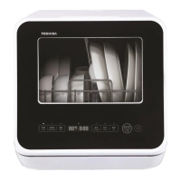
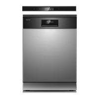
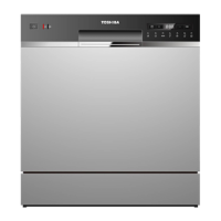
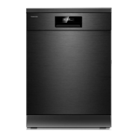
| Model | DWS-22A Series |
| Category | Dishwasher |
| Language | English |