Do you have a question about the Toshiba HWT-602S21SM3W-E(TR) and is the answer not in the manual?
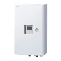
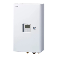
Detailed specifications for the Hydro unit, including dimensions, electrical characteristics, and performance data.
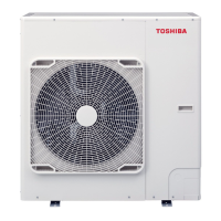
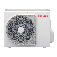
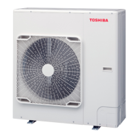
Detailed specifications for the Outdoor unit, including dimensions, electrical characteristics, and performance data.
External views and dimensions of the Hydro unit, showing connection ports and required clearances.
External views and dimensions of the Outdoor unit, indicating mounting points, ports, and overall size.
Diagram illustrating the water circuit of the heat pump system, including pumps, valves, and heat exchangers.
Diagram showing the refrigeration cycle components, including compressor, heat exchanger, and valves.
Detailed wiring diagram for the Hydro unit, showing connections to sensors, pumps, valves, and control boards.
Detailed wiring diagram for the Outdoor unit, illustrating connections to compressor, fan motor, sensors, and control boards.
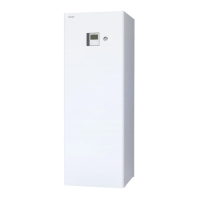
Wiring diagram for the hot water cylinder unit, showing connections to heater and sensors.
List of key electrical components in the Hydro unit with their model names, types, and ratings.
List of key electrical components in the Outdoor unit with their model names, types, and ratings.
List of electrical components for the hot water cylinder unit with their model names, types, and ratings.
Identification of connectors and components on the Water heat exchange control board (MCC-1753).
Identification of connectors and components on the Outdoor control board (MCC-1768).
Essential safety precautions for handling R32 refrigerant during installation and servicing.
Guidelines for installing refrigerant piping, including materials and processing methods.
Step-by-step procedure for recharging refrigerant, including necessary precautions.
Procedures and materials required for brazing refrigerant pipes, focusing on preventing oxidation.
Guidelines for reusing existing R22 or R407C piping for R32 models, including restrictions.
Comprehensive safety measures related to R32 refrigerant, including recovery and decommissioning.
Describes the fundamental operations of the heat pump system, including heating, cooling, and hot water supply.
Details various operation modes, control methods, and performance ranges based on conditions.
Explains the control functions of the Hydro unit, including compressor, heater, and pump operations.
Explains the control functions of the Outdoor unit, including fan, compressor, and valve operations.
Initial checks and confirmations required before diagnosing a failure in the heat pump system.
Overview of the diagnostic determination process and how to interpret check codes.
Detailed flow charts for diagnosing failures based on specific check codes for Hydro and Outdoor units.
Procedures for checking component operations using PC board switches in a specific mode.
Methods for checking the resistance values of key components in the Hydro unit.
Configuration settings (DN codes) for the Hydro unit, affecting its operation and features.
Procedures for setting DN codes for the Hydro Unit and Remote Controller.
Procedure for replacing the Hydro unit Main PC board, including setting DN codes.
Procedure for replacing the Outdoor unit PC board, including setting jumper wires.
Step-by-step instructions for detaching and attaching major parts of the Hydro unit.
Step-by-step instructions for detaching and attaching major parts of the Outdoor unit.
Periodic inspection details for the Hydro unit, covering electrical, refrigerant, and water systems.
Periodic inspection details for the Outdoor unit, covering electrical, refrigerant, and fan systems.
Periodic inspection details for the Hot water cylinder, covering insulation, leakage, and assembly.
Visual exploded views and lists of parts for the Hydro unit assembly.
Part list for various Outdoor unit models, detailing component numbers and quantities.
Exploded views and part identification for the Inverter assembly components.
Detailed procedure for replacing the Hydro unit Main PC board assembly.
Step-by-step guide for replacing the MCC-1768 PC board, including jumper wire settings.
Step-by-step guide for replacing the MCC-1675 PC board, including jumper wire settings.





 Loading...