Do you have a question about the Toshiba Libretto 50CT and is the answer not in the manual?
Information in this manual is subject to change without notice.
Lists registered trademarks of various companies.
Details DANGER, WARNING, CAUTION, and NOTE messages for safe maintenance.
Describes the system unit and each FRU.
Explains how to diagnose and resolve FRU problems.
Describes how to perform test and diagnostic operations.
Describes the removal and replacement of FRUs.
Lists various appendices including handling, layout, wiring, and reliability.
Explains how acronyms, keys, and input/display formats are presented.
Details the key features and benefits of the Libretto 50CT/70CT.
Provides a block diagram of the computer's system unit components.
Describes the 3.5-inch external FDD and its specifications.
Describes the 2.5-inch Hard Disk Drive and its capacities.
Details the keyboard specifications and features.
Provides specifications for the LCD module and its display capabilities.
Explains power supply functions and lists output ratings.
Describes main and RTC batteries, and the charging control process.
Identifies FRUs causing malfunctions and lists necessary troubleshooting tools.
Provides a flowchart to guide troubleshooting steps for computer malfunctions.
Guides on checking power supply status, error codes, and connections.
Describes how to determine if the system board is defective or not functioning properly.
Guides on determining if the 3.5-inch FDD is functioning properly.
Provides procedures to determine if the hard disk drive is functioning properly.
Describes how to determine if the keyboard is functioning properly.
Guides on determining if the pointing device is functioning properly.
Describes how to determine if the display is functioning properly.
Explains the Diagnostic Test Program, its menu, and available functional tests.
Provides steps to start and navigate the Diagnostics Program menu.
Lists subtest names for each program on the Diagnostic Test Menu.
Explains the System Test, including the ROM checksum subtest.
Details six subtests for testing the computer's memory.
Covers tests for the keyboard, PS/2 mouse, and AccuPoint actions.
Details six subtests to test the display in various modes.
Explains how to perform tests on the FDD, including reading and writing.
Details three subtests to check printer output and functions.
Covers seven subtests for asynchronous communication functions.
Explains how to execute ten subtests to check hard disk drive functions.
Describes three subtests for testing real timer functions, including date/time input.
Explains a subtest for checking coprocessor functions.
Describes a subtest for checking PCMCIA wraparound and signal lines.
Details two subtests for testing sound functions, FM synthesizer and sine-wave playback.
Lists error codes and their status names for various diagnostic tests.
Explains how to interpret HDC status and error registers for hard disk tests.
Describes low-level and MS-DOS logical formatting for the hard disk.
Explains the procedure for cleaning FDD heads using a cleaning kit.
Describes how the Log Utilities function logs and stores error information.
Details the automatic execution sequence of various diagnostic tests.
Covers formatting, copying, and dumping functions for floppy disks.
Displays configuration info for BIOS, memory, drives, ports, and CPU clock.
Details system setup options for Memory, Display, Hard Disk, I/O Ports, and Others.
Explains how to disassemble the computer and replace Field Replaceable Units (FRUs).
Provides DANGER, WARNING, and CAUTION precautions for disassembly and component handling.
Advises on preparation, tool usage, and working environment for disassembly.
Describes three basic types of cable connectors and their handling.
Provides general points for reassembling the computer after repairs.
Lists essential ESD equipment and tools needed for repairs.
Specifies torque values for various screw sizes to prevent damage.
Details how to remove and install the main battery pack.
Explains how to remove and install an optional PC card.
Details how to remove and install the 2.5-inch Hard Disk Drive.
Explains how to remove and install an optional memory module.
Details how to remove and install the keyboard.
Explains how to remove and install the display assembly.
Details how to remove and install the RTC battery.
Explains how to remove and install the system board.
Details how to remove and install the display mask.
Explains how to remove and install the FL inverter board.
Details how to remove and install the LCD module.
Explains how to remove and install the power switch board.
Details how to remove and install the AccuPoint board.
Explains how to remove and install the LCD flexible cable.
Details how to remove and install the I/O adapter board.
Provides precautions to avoid damaging the LCD module during handling.
Shows the layout of components on the system board.
Lists pin assignments for various connectors on the system board.
Shows the key layouts for different regional keyboards.
Provides wiring diagrams for connectors and cables.
Provides step-by-step instructions for updating the system BIOS.
Shows Mean Time Between Failures (MTBF) for various computer components.
| Manufacturer | Toshiba |
|---|---|
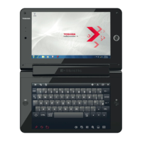
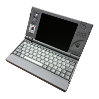
| Model | Libretto 50CT |
| Category | Laptop |
| Release Year | 1997 |
| Operating System | Windows 95 |
| Graphics | Integrated |
| Display | 640x480 |
| Weight | 840 g |
| Dimensions | 210 x 115 x 34 mm |
| Battery | Lithium-ion |
| Ports | Serial, Parallel |
| RAM | 16 MB (upgradable to 32MB or 48MB) |