EasyManua.ls Logo

Toshiba MMD-AP0076BHP1-E User Manual

Toshiba MMD-AP0076BHP1-E
105 pages
To Next Page IconTo Next Page
Page #1 background imageLoading...
Page #1 background image
R410A
FILE NO. SVM-16043
SERVICE MANUAL
AIR-CONDITIONER
MULTI TYPE
INDOOR UNIT
< Concealed Duct Standard Type >
MMD-AP0076BHP1-E
MMD-AP0096BHP1-E
MMD-AP0126BHP1-E
MMD-AP0156BHP1-E
MMD-AP0186BHP1-E
MMD-AP0246BHP1-E
MMD-AP0276BHP1-E
MMD-AP0306BHP1-E
MMD-AP0366BHP1-E
MMD-AP0486BHP1-E
MMD-AP0566BHP1-E
MMD-AP0076BHP1-TR
MMD-AP0096BH
P1-TR
MMD-AP0126BHP1-TR
MMD-AP0156BHP1-TR
MMD-AP0186BHP1-TR
MMD-AP02
46BHP1-TR
MMD-AP0276BHP1-TR
MMD-AP0306BHP1-TR
MMD-AP0366BHP1-TR
MMD-AP0486BHP1-TR
MMD-AP0566BHP1-TR
April
201
6

Table of Contents

Question and Answer IconNeed help?

Do you have a question about the Toshiba MMD-AP0076BHP1-E and is the answer not in the manual?

Toshiba MMD-AP0076BHP1-E Specifications

General IconGeneral
Cooling Capacity (kW)2.2
Heating Capacity (kW)2.5
Power Supply220-240V, 50Hz
RefrigerantR32
Energy Efficiency Ratio (EER)3.21
Coefficient of Performance (COP)3.61
Indoor Unit Weight9 kg
TypeSplit System

Summary

Definition of Qualified Installer or Qualified Service Person

Agent Qualifications and Knowledge

Details qualifications and knowledge required for installers and service personnel.

Definition of Protective Gear

Explanation of Indications

Explains the meaning of danger, warning, and caution symbols used in the manual.

Explanation of Illustrated Marks

Clarifies the meaning of prohibited, mandatory, and cautious illustrated marks.

Warning Indications on the Air Conditioner Unit

Confirmation of Warning Labels

Confirms that all safety warning labels are correctly indicated on the unit.

Precautions for Safety

DANGER - Critical Safety Warnings

Details critical safety warnings regarding electrical shock, parts, and operation.

General Safety Warnings

Check Earth Wires for Safety

Emphasizes proper grounding procedures to prevent electric shock.

Safety Prohibitions and Refrigerant Handling

Refrigerant Safety and Handling

Details precautions for handling R410A refrigerant to prevent accidents.

Assembly, Repair, and Reinstallation Safety

Post-Repair Safety Checks

Outlines essential checks after repair work for safety and proper function.

Installation and Operation Safety

Installation Safety Guidelines

Provides essential safety guidelines for installing the air conditioner unit.

Declaration of Conformity

Specifications

Sound Pressure Level and Weight

Lists sound pressure levels (dBA) and main unit weights for various models.

Specifications (50Hz)

Electrical Characteristics and Dimensions (50Hz)

Details power supply, current, dimensions, and weights for 50Hz models.

Specifications (60Hz)

Electrical Characteristics and Dimensions (60Hz)

Details power supply, current, dimensions, and weights for 60Hz models.

Air Ducting Work Performance

Airflow Data for AP007-AP0276 Models

Graphs showing external static pressure vs. air volume for specific models.

Air Ducting Work Performance

Airflow Data for AP0306-AP0566 Models

Graphs showing external static pressure vs. air volume for specific models.

Construction Views and Dimensions

External Dimensions and Key Features

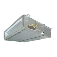
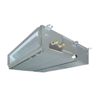
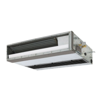
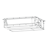
Provides diagrams and dimension tables for various model types.

Detailed Construction Views

Unit Construction Diagrams

Illustrates internal construction details for different model series.

Wiring Diagrams

Indoor Unit Wiring Diagram

Shows the electrical connections for the indoor unit.

Parts Ratings

Component Specifications

Lists ratings for fan motors, drain pumps, sensors, and other components.

Refrigerant Cycle Diagram

Explanation of Functional Parts

Describes the function of key components in the indoor unit's refrigerant cycle.

Indoor Unit Control Outline

Power Reset and Operation Selection

Details unit identification on reset and mode selection via remote controller.

Indoor Unit Control Logic

Fan Speed Control Logic

Explains fan speed adjustments in cooling and heating based on temperature.

Indoor Unit Control Modes

Cold Air Discharge & Freeze Prevention

Describes controls for preventing cold air and managing freeze conditions.

Indoor Unit Operational Controls

Refrigerant Recovery and Defrosting Control

Details refrigerant recovery, defrosting, and drain pump control functions.

System Status and Control Modes

Operation Standby and Central Control

Explains standby modes and selection of central control operations.

Operational Features and Test Procedures

Test Run and Power Saving Mode

Describes test run procedures and power saving mode functions.

Applied Control and Circuit Configuration

Wired Remote Controller Block Diagram

Illustrates the indoor controller block diagram for wired remote setup.

Applied Control Systems

Wireless Remote Controller Configuration

Shows the block diagram for connecting a wireless remote controller.

Integrated Control System Configurations

Wired and Wireless Remote Controller Connection

Depicts the block diagram for connecting both wired and wireless controllers.

Indoor Print Circuit Board Details

MCC-1631 PCB Layout

Shows the physical layout and component labeling of the indoor PCB.

Indoor PC Board Connector Specifications

Optional Connector Functions and Pins

Details specifications for optional connectors and their functions.

Indoor Unit Test Operation

Test Operation Procedure and Outcomes

Explains how to perform a test operation and expected results.

Setting Indoor Unit Functions via DN Code

Procedure for DN Code Setting

Step-by-step guide to set function DN codes using a wired remote controller.

DN Code Function Table

DN Code Descriptions and Settings

Lists DN codes, their functions, default settings, and parameters.

DN Code Configuration Details

Type and Capacity DN Codes

Specifies DN codes for unit type and capacity selection.

Applied Indoor Unit Control Systems

Remote Controller Interface Control

Explains control system using the TCB-IFCB4E2 interface.

Ventilating Fan Control

Ventilating Fan Control Wiring and Operation

Details how to control the ventilating fan via remote and its wiring.

Advanced Indoor Unit Control Functions

Leaving-ON Prevention and Power Peak-Cut

Describes functions for preventing unintended operation and managing power usage.

Manual Address Setting

Remote Controller Address Setting Procedure

Step-by-step guide for setting unit addresses via remote controller.

Address Setting Details and Notes

Setting Line, Unit, and Group Addresses

Details how to set various addresses and important notes.

Confirming Unit Addresses and Positions

Checking Unit Addresses with Remote Controller

Procedure to check indoor unit addresses and their positions.

Finding Unit Positions from Addresses

Checking Unit Numbers in Group Control

Method to find unit positions when controlled as a group.

Checking All Unit Addresses

Checking Addresses via Wired Remote Controller

Procedure to check all indoor unit addresses using a wired remote controller.

Changing Indoor Unit Addresses

Procedure for Changing Unit Addresses

Step-by-step guide to change indoor unit addresses via remote controller.

Modifying All Indoor Unit Addresses

Changing Addresses with Wired Remote Controller

Method to change all indoor unit addresses using a wired remote controller.

Address Modification Process

Updating Indoor Unit Address Values

Details how to change the indoor unit address values in SET DATA.

Error Clearing Function

Clearing Outdoor and Indoor Unit Errors

Instructions for clearing errors for both outdoor and indoor units.

Monitoring Functions

Service Monitoring Mode Operation

How to enter service monitoring mode to check sensor temps and operation status.

Target Outdoor Unit Data (SMMS Series)

Indoor and System Unit Data Codes

Lists data codes for indoor and system units for SMMS series.

Target Outdoor Unit Data (SMMS-i Series)

Indoor and Individual Unit Data Codes

Lists data codes for indoor and individual outdoor units for SMMS-i series.

Outdoor Unit Data and LED Indicators

LED Display of Circuit Board

Explains the meaning of LED indicators on the circuit board.

Troubleshooting Overview

Troubleshooting Preparation and Procedure

Lists required tools and the basic troubleshooting flow.

Troubleshooting Methods

Check Codes for Indoor Units

Lists error codes detected by the indoor unit and their causes.

Troubleshooting Check Codes

Errors Detected by Remote/Central Control

Lists error codes detected by main remote and central control devices.

Troubleshooting Outdoor Unit Errors

Check Codes for Outdoor Units (SMMS Examples)

Lists error codes detected by outdoor unit interface for SMMS.

Outdoor Unit Error Diagnosis

Detailed Outdoor Unit Check Codes

Provides further details on outdoor unit error codes and their causes.

Comprehensive Outdoor Unit Error Codes

IPDU and Other Outdoor Unit Errors

Details errors related to IPDU and other outdoor unit components.

Advanced Outdoor Unit Error Analysis

IPDU and Compressor Specific Errors

Lists errors specific to IPDU and compressor circuits.

Troubleshooting via Remote Controller Display

Using Main Remote Controller (RBC-AMT32E)

Guide to interpret error codes and history on the main remote controller.

Troubleshooting with TCC-LINK Controller

Using TCC-LINK Central Controller

Guide to interpret error codes and history on the TCC-LINK controller.

Troubleshooting via Indoor Unit Indicators

Interpreting Light Block Indicators

Maps light block states to check codes and fault causes.

Indoor Unit Indicator Fault Diagnosis

Light Block Error Code Mapping

Details error codes linked to light block status and fault causes.

Additional Indicator Fault Diagnosis

Interpreting Non-Check Code Indicators

Explains indicators for test run and setting incompatibility.

Check Codes and Troubleshooting Locations

Remote Controller and Outdoor Unit Display Codes

Maps check codes from remote and outdoor displays to locations for checks.

Detailed Check Code Troubleshooting

Outdoor Unit Communication and Address Errors

Details check codes related to communication and address issues.

Outdoor Unit Communication Troubleshooting

Outdoor Unit Communication and Address Errors

Focuses on errors related to outdoor unit communication and address settings.

IPDU and Sensor Error Troubleshooting

IPDU and Indoor Sensor Errors

Details errors related to IPDU and indoor unit sensors.

Outdoor Sensor and Wiring Troubleshooting

Outdoor Sensor and Wiring Errors

Covers errors related to outdoor sensors and wiring.

Compressor and Power System Troubleshooting

Compressor, Power, and Sensor Errors

Details errors related to compressor, power, and sensors.

Oil Level and Sensor Error Troubleshooting

Oil Level and Temperature Sensor Errors

Covers errors related to oil level detection and temperature sensors.

Refrigerant and Temperature Troubleshooting

Refrigerant Flow and Temperature Sensor Errors

Details errors related to refrigerant flow and temperature sensors.

Oil Circuit and Refrigerant Troubleshooting

Oil Circuit and Refrigerant Detection Errors

Covers errors in oil circuits and refrigerant detection.

Unit Mismatch and Address Error Troubleshooting

Unit Mismatch and Address Errors

Details errors related to unit mismatch and address settings.

IPDU and Unit Connection Troubleshooting

IPDU, Unit Connection, and Address Errors

Covers errors related to IPDU, unit connections, and addresses.

Pressure and Refrigerant Flow Troubleshooting

Pressure and Refrigerant Flow Errors

Details errors related to pressure sensors and refrigerant flow.

High Pressure and Overflow Troubleshooting

High Pressure and Overflow Errors

Covers errors related to high pressure and overflow conditions.

Refrigerant Leak and Temperature Errors

Refrigerant Leak and Temperature Sensor Errors

Details errors related to refrigerant leaks and temperature sensors.

Valve and Pressure Protection Troubleshooting

Valve Reversing and Pressure Protection Errors

Covers errors related to 4-way valve reversing and high-pressure protection.

Fan IPDU and Motor Troubleshooting

Fan IPDU and Motor Operation Errors

Details errors related to fan IPDU and motor operation.

Fan and Compressor Protection Troubleshooting

Fan, Compressor Protection, and Other Errors

Covers errors related to fan, compressor protection, and other indoor unit issues.

TCC-LINK Central Control Errors

Central Control Communication and Duplication Errors

Lists errors related to central control communication and address duplication.

Fan Motor Checking Procedures

Fan Motor Resistance Measurement

Details how to measure fan motor winding resistance.

Sensor Characteristics

Indoor Temperature Sensor Characteristics

Provides resistance vs. temperature data for indoor TA, TC1, TC2, TCJ sensors.

PC Board Exchange Procedures

Indoor PC Board Replacement

Outlines procedures and notes for replacing indoor PC boards.

EEPROM Handling and Replacement

EEPROM Layout and Replacement Methods

Describes EEPROM location, removal, and replacement methods.

EEPROM Data Reading Procedure

Reading Setting Data from EEPROM

Step-by-step guide to read setting data from EEPROM using the remote controller.

PC Board Replacement Procedure

Replacing the PC Board and Establishing Correspondence

Details the process of replacing the PC board and ensuring unit-remote controller correspondence.

Writing EEPROM Data

Writing Setting Data into EEPROM

Step-by-step guide to write setting data into the new EEPROM.

DN Code Reference List

DN Code Items and Settings

Lists DN codes, their items, setting data, and factory values.

Detachment and Attachment Procedures

Air Filter Removal and Installation

Instructions for detaching and attaching the air filter.

Component Removal and Installation

Suction Panel and Electric Parts Box Cover

Details removal and installation of the suction panel and electric parts box cover.

Internal Component Removal

Electric Parts Box and Control PC Board Removal

Instructions for removing the electric parts box and control PC board.

Motor Component Removal

PMV Motor Removal

Steps for detaching and removing the PMV motor.

Fan Assembly Removal and Installation

Fan Motor, Fan, and Case Procedures

Instructions for detaching and attaching the fan motor, fan, and case.

Drain System Component Handling

Drain Pan, Pump, and Float Switch Procedures

Details removal and installation of drain pan, pump, and float switch.

Heat Exchanger Servicing

Heat Exchanger Removal and Installation

Steps for removing and installing the heat exchanger.

Exploded Views and Parts List

Exploded View for Concealed Duct Standard Type

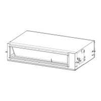
Exploded diagram showing parts for specific concealed duct models.

Parts List for Concealed Duct Standard Type

Parts List (AP007-AP0186)

Lists part numbers and quantities for specific models.

Exploded Views for Larger Capacity Models

Exploded View (AP0246-AP0306)

Exploded diagram showing parts for larger capacity concealed duct models.

Parts List for Larger Capacity Models

Parts List (AP0246-AP0306)

Lists part numbers and quantities for larger capacity models.

Exploded Views for Highest Capacity Models

Exploded View (AP0366-AP0566)

Exploded diagram showing parts for the highest capacity concealed duct models.

Parts List for Highest Capacity Models

Parts List (AP0366-AP0566)

Lists part numbers and quantities for the highest capacity models.

Parts List for Control Components

List of Service Sensors and Clamps

Lists part numbers for service sensors and clamps.

Related product manuals