EasyManua.ls Logo

Toshiba MMD-AP0366BHP1-E User Manual

Toshiba MMD-AP0366BHP1-E
105 pages
To Next Page IconTo Next Page
Page #1 background imageLoading...
Page #1 background image
R410A
FILE NO. SVM-16043
SERVICE MANUAL
AIR-CONDITIONER
MULTI TYPE
INDOOR UNIT
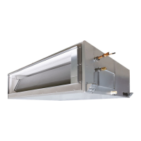
< Concealed Duct Standard Type >
MMD-AP0076BHP1-E
MMD-AP0096BHP1-E
MMD-AP0126BHP1-E
MMD-AP0156BHP1-E
MMD-AP0186BHP1-E
MMD-AP0246BHP1-E
MMD-AP0276BHP1-E
MMD-AP0306BHP1-E
MMD-AP0366BHP1-E
MMD-AP0486BHP1-E
MMD-AP0566BHP1-E
MMD-AP0076BHP1-TR
MMD-AP0096BH
P1-TR
MMD-AP0126BHP1-TR
MMD-AP0156BHP1-TR
MMD-AP0186BHP1-TR
MMD-AP02
46BHP1-TR
MMD-AP0276BHP1-TR
MMD-AP0306BHP1-TR
MMD-AP0366BHP1-TR
MMD-AP0486BHP1-TR
MMD-AP0566BHP1-TR
April
201
6

Table of Contents

Question and Answer IconNeed help?

Do you have a question about the Toshiba MMD-AP0366BHP1-E and is the answer not in the manual?

Toshiba MMD-AP0366BHP1-E Specifications

General IconGeneral
BrandToshiba
ModelMMD-AP0366BHP1-E
CategoryAir Conditioner
LanguageEnglish

Summary

Definition of Qualified Installer or Qualified Service Person

Definition of Protective Gear

Warning Indications on the Air Conditioner Unit

Confirmation of warning label on the main unit

Instruction to verify the presence and placement of warning labels on the unit.

PRECAUTIONS FOR SAFETY

DANGER

Severe warnings about immediate and serious hazards requiring utmost caution.

WARNING

Warnings about potential hazards that could cause death or serious injury.

General

General safety guidelines, including protective gear and work procedures.

Check earth wires.

Importance of proper grounding to prevent electric shock hazards.

Specifications

WIRING DIAGRAMS

PARTS RATING

APPLIED CONTROL AND FUNCTIONS (INCLUDING CIRCUIT CONFIGURATION)

TROUBLESHOOTING

9-1. Overview

Introduction to troubleshooting, including models, tools, and initial checks.

9-2. Troubleshooting method

Guidance on interpreting check codes and identifying faults.

9-3. Troubleshooting based on information displayed on remote controller

How to diagnose faults using remote controller displays and error history.

9-4. Check codes displayed on remote controller and SMMS outdoor unit

Detailed list of check codes and their causes/locations.

P.C. BOARD EXCHANGE PROCEDURES

10-1. Replacement of indoor P.C. boards

Step-by-step guide for replacing the indoor P.C. board assembly.

Points to note when replacing indoor P.C. board assembly

Critical considerations, including EEPROM data handling, before replacing the P.C. board.

Procedure 1: reading setting data from EEPROM

Instructions to read factory and site-specific settings from the EEPROM using the remote controller.

Procedure 2: replacing P.C. board

Steps for physically replacing the P.C. board and establishing controller correspondence.

Procedure 3: writing setting data in EEPROM

Instructions to write configuration data into the new EEPROM via the remote controller.

EXPLODED VIEWS AND PARTS LIST

Related product manuals