EasyManua.ls Logo

Toshiba MMD-AP0966HP-E User Manual

Toshiba MMD-AP0966HP-E
98 pages
To Next Page IconTo Next Page
Page #1 background imageLoading...
Page #1 background image
R410A
FILE NO. SVM-16013
SERVICE MANUAL
AIR-CONDITIONER
MULTI TYPE
MMD-AP0726HP-E
MMD-AP0966HP-E
MMD-AP0726HP-TR
MMD-AP0966HP-TR
INDOOR UNIT
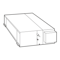
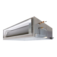
< Concealed Duct High Static Pressure Type >
AMP Air Conditioning
www.ampair.co.uk | sales@ampair.co.uk

Other manuals for Toshiba MMD-AP0966HP-E

Questions and Answers:

Toshiba MMD-AP0966HP-E Specifications

General IconGeneral
BrandToshiba
ModelMMD-AP0966HP-E
CategoryAir Conditioner
LanguageEnglish

Summary

Definition of Qualified Installer or Qualified Service Person

Definition of Protective Gear

Warning Indications on the Air Conditioner Unit

PRECAUTIONS FOR SAFETY

DANGER and WARNING Explanations

Explains the meaning and significance of DANGER and WARNING symbols.

General Safety Guidelines

Provides general safety instructions and warnings for safe operation.

Refrigerant Safety Precautions

Details critical safety measures related to handling refrigerants.

Installation and Relocation Safety

Outlines safety requirements for installation and relocation procedures.

Declaration of Conformity

1. SPECIFICATIONS

Model Specifications Overview

Provides a summary table of specifications for different models.

Detailed Technical Specifications

Lists detailed technical data including capacity, power, and dimensions.

2. FAN CHARACTERISTICS

3. CONSTRUCTION VIEWS (EXTERNAL VIEWS)

Unit Dimensions and Port Locations

Shows external dimensions and locations of pipes and ports.

Duct Arrangement and Airflow Paths

Illustrates duct connections and airflow paths for unit installation.

4. WIRING DIAGRAMS

5. PARTS RATING

6. REFRIGERANT CYCLE DIAGRAM

Indoor Unit Refrigerant Flow

Illustrates the refrigerant path and key components within the indoor unit.

Functional Parts Explanation

Explains the function and outline of major parts in the refrigerant cycle.

7. CONTROL OUTLINE

Power Reset and Operation Selection

Details unit behavior after power reset and operational mode selection.

Temperature and Capacity Control

Explains temperature control ranges and automatic capacity adjustment.

Fan Speed Control Logic

Describes how fan speed is adjusted based on temperature differences.

Cold Air Discharge and Freeze Prevention

Explains controls for preventing cold air discharge and freeze-ups.

Refrigerant Recovery and Defrosting Control

Outlines procedures for refrigerant recovery and defrosting operations.

Filter and Standby Operation Modes

Explains filter status display and standby modes like heating standby.

Central Control Mode Selection

Details settings for central control and remote operation capabilities.

8. APPLIED CONTROL AND FUNCTIONS (INCLUDING CIRCUIT CONFIGURATION)

Indoor Controller Block Diagrams

Shows block diagrams for wired, wireless, and combined remote controller connections.

Indoor Circuit Design Board Details

Provides detailed information and diagrams of the indoor circuit board.

Optional Connector Specifications

Lists specifications for optional connectors on the indoor circuit board.

Fan IPDU and Noise Filter Boards

Describes the Fan IPDU and Noise Filter P.C. boards.

Indoor Unit Test Operation

Explains how to perform a test operation of the indoor unit.

Indoor Unit Function DN Code Setting

Guides on how to set indoor unit functions using DN codes.

Remote Location ON/OFF Control System

Details the control system using a remote location ON/OFF box.

Ventilating Fan Control from Remote Controller

Explains how to control the ventilating fan via the remote controller.

Leaving-ON Prevention Control

Describes the function to prevent units from staying on unnecessarily.

Power Peak-Cut from Indoor Unit

Explains how to implement power peak-cut from the indoor unit.

Manual Address Setting Using the Remote Controller

Guides on manually setting indoor unit addresses using the remote controller.

Confirming Indoor Unit Addresses

Explains how to check indoor unit addresses and positions via the remote controller.

Check Code Clearing Function

Details the procedure for clearing check codes from the remote controller.

Monitoring Function of Wired Remote Controller

Describes the monitoring capabilities of the wired remote controller.

System Data Display

Explains various system data displayed on the remote controller.

9. TROUBLESHOOTING

Troubleshooting Overview and Procedure

Provides an overview of troubleshooting steps and common issues.

Troubleshooting Method using Check Codes

Explains how to use check codes to diagnose problems.

Troubleshooting via Remote Controller Display

Guides on troubleshooting based on information shown on the remote controller.

Troubleshooting with Wireless Indicators

Details troubleshooting using indoor unit indicator lights.

Check Codes: Locations and Causes

Lists check codes, locations, system status, and potential causes.

Sensor Characteristics for Diagnostics

Provides resistance characteristics of sensors for troubleshooting.

10. REPLACEMENT OF SERVICE P.C. BOARD

Indoor Circuit Design Board Replacement

Step-by-step guide for replacing the indoor P.C. board.

EEPROM Data Handling Procedures

Details procedures for reading and writing EEPROM data during board replacement.

Fan IPDU P.C. Board Replacement

Instructions for replacing the Fan IPDU P.C. board.

Noise Filter P.C. Board Replacement

Procedure for replacing the Noise Filter P.C. board.

11. DETACHMENTS

Electrical Parts Box Cover Removal

Procedure for detaching the electrical parts box cover.

Control P.C. Board Removal

Steps for removing the control P.C. board.

Fan Control P.C. Board Removal

Instructions for detaching the fan control P.C. board.

Noise Filter P.C. Board Removal

Procedure for removing the noise filter P.C. board.

PMV Motor Removal

Steps for detaching and removing the PMV motor.

Suction Panel Removal

Procedure for removing the suction panel.

Fan Motor Removal

Detailed steps for removing the fan motor assembly.

Drain Pan Removal

Procedure for detaching and removing the drain pan.

Sensor TC1, TC2, TCJ Removal

Steps for removing the TC1, TC2, and TCJ sensors.

Heat Exchanger Removal

Procedure for removing the heat exchanger assembly.

Sensor TA Removal

Steps for detaching and removing the TA sensor.

Reactor Removal

Procedure for removing the reactor component.

12. EXPLODED VIEWS AND PARTS LIST

Exploded View: Main Unit Components

Illustrated breakdown of major components for specific models.

Drain Pump Kit Parts List

Lists parts included in the drain pump kit.

Electric Parts List

Details electrical components and their part numbers.

WARNINGS ON REFRIGERANT LEAKAGE

Check of Concentration Limit

Explains concentration limits for refrigerant leakage in different room types.

Minimum Room Volume Standards

Outlines standards for minimum room volume based on refrigerant charge.

Related product manuals