Do you have a question about the Toshiba MMK-UP0241HP-E and is the answer not in the manual?
Specifications for 4-way cassette type indoor units, including cooling/heating capacity and dimensions.
Specifications for Ceiling type indoor units, covering capacity, electrical characteristics, and dimensions.
Specifications for Concealed Duct Standard type units, detailing capacity, electrical features, and physical dimensions.
Specifications for Concealed Duct High Static Pressure type units, including capacity, electrical data, and dimensions.
Specifications for Concealed Duct High Static Pressure fresh air intake units, covering performance and physical data.
Specifications for Console type units, detailing cooling/heating capacity, electrical characteristics, and dimensions.
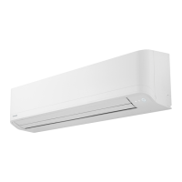
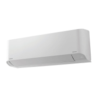
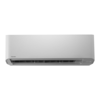
Specifications for High Wall type units, including capacity, electrical data, dimensions, and sound levels.
External views and installation dimensions for 4-way cassette type indoor units.
External views and installation dimensions for Ceiling type indoor units.
External views and dimensions for Concealed Duct Standard type units, including installation space.
External views and dimensions for Concealed Duct High Static Pressure type units.
External views and dimensions for Concealed Duct High Static Pressure fresh air intake type units.
External views and installation dimensions for Console type indoor units.
External views and installation dimensions for High Wall type indoor units.
Wiring diagram for 4-way cassette type indoor units, illustrating connections and components.
Wiring diagram for Ceiling type indoor units, showing electrical connections and component layout.
Wiring diagram for Concealed Duct Standard type units, detailing electrical connections.
Wiring diagram for Concealed Duct High Static Pressure type units.
Wiring diagram for Concealed Duct High Static Pressure fresh air intake type units.
Wiring diagram for Console type indoor units, illustrating connections.
Wiring diagram for High Wall type indoor units, showing electrical connections.
Parts list for 4-way cassette type indoor units, detailing fan motor, P.C. board, and sensors.
Parts list for Ceiling type indoor units, including fan motor, P.C. board, and sensors.
Parts list for Concealed Duct Standard type units, including fan motor, P.C. board, and sensors.
Parts list for Concealed Duct High Static Pressure type units.
Parts list for Concealed Duct High Static Pressure fresh air intake type units.
Parts list for Console type indoor units, detailing components like fan motor and sensors.
Parts list for High Wall type indoor units, including fan motor, sensors, and P.C. boards.
Explanation of functional parts in the indoor unit, detailing components like PMV and sensors.
Details on control specifications including power reset behavior and operation mode selection.
Information on room temperature control settings, including wired and wireless remote controller ranges.
Details on fan speed selection modes (AUTO, HH, H+, H, L+, L, UL) and their operation.
Procedure for preventing cold air discharge by controlling fan speed based on temperature zones.
Controls for preventing freeze-up during cooling, detailing reset conditions based on sensor readings.
Controls for refrigerant oil recovery during stop/thermostat OFF or FAN operation in cooling mode.
Controls for refrigerant oil recovery during stop/thermostat OFF or FAN operation in heating mode.
Ensures continuous operation for 3 minutes after start, even if thermostat-OFF condition occurs.
Operation of the drain pump during cooling, DRY, and stop states, including float switch logic.
Indoor fan operation for 30 seconds with [L] after stopping from HEAT operation.
ON/OFF operation control via HA signal from remote site or remote ON/OFF interface.
Function of the filter sign display, indicating filter status and integrated operation time.
Display indicators on the remote controller for READY and HEAT READY status.
Selection of operable modes via central controller, defining setting contents for group control.
Setup of louver position for normal, cooling/dry, and heating/fan operations, including group control.
Procedure for setting individual air direction for each discharge port using the louver select button.
Selection of swing modes (Standard, Dual, Cycle) and their settings via remote controller or data.
Procedure for locking louver position for air direction setup and registering setup data.
Block diagram of the indoor controller (MCC-1643) for various connection types.
Block diagram showing the connection of a wireless remote controller to the indoor unit.
Block diagram illustrating the connection of both wired and wireless remote controllers.
Block diagram of the indoor controller (MCC-1720) for different remote controller connections.
Block diagram for MCC-1720 controller with wired remote controller connection.
Block diagram for MCC-1720 controller with wireless remote controller connection.
Block diagram for MCC-1720 controller connecting both wired and wireless remote controllers.
Block diagram of the indoor controller (MCC-1696) for wired and wireless remote controllers.
Block diagram for MCC-1696 controller with wired remote controller connection.
Block diagram for MCC-1696 controller with wireless remote controller connection.
Details of the indoor unit's print circuit board (MCC-1643), showing component locations.
Detailed view of the MCC-1643 print circuit board with component labels.
Detailed view of the MCC-1720 print circuit board with component labels.
Detailed view of the MCC-1696 print circuit board with component labels.
Core operational check procedure for performing cooling and heating test runs.
Procedure for performing cooling and heating test runs using the remote controller.
Configuration procedure for setting indoor unit functions and DN codes via remote controller.
Details on applying control systems, including remote location ON/OFF control box.
Wiring and setting for control system using Remote location ON/OFF control box.
Procedure for controlling the ventilating fan using the wired remote controller.
Functionality for controlling indoor units automatically, useful for stop operations.
Feature for managing power consumption, initiating forced thermostat OFF operation.
Function dedicated to TU2C-Link communication for issuing notice codes.
Procedure for manually setting indoor unit addresses via remote controller.
Procedure to check indoor unit addresses and their positions using the remote controller.
Procedure to check the number and positions of indoor units, and system address recognition.
Method to identify indoor unit addresses and their positions within a group.
Procedure to find indoor unit positions when controlled as a group using the remote controller.
Method to change all indoor unit addresses across refrigerant lines using a wired remote controller.
Procedure for changing the address of an individual or group indoor unit via remote controller.
Procedures for clearing check codes from outdoor and indoor units using the remote controller.
Procedure to clear outdoor unit check codes using the service monitoring function on the wired remote controller.
Procedure to clear the check code of the indoor unit using the remote controller's ON/OFF button.
Functionality for checking sensor temperatures and operation status of units via remote controller.
List of data points and display formats for monitoring indoor unit sensors and operation status.
General overview of troubleshooting procedures, applicable models, and required tools.
Detailed troubleshooting guide based on check codes detected by various devices.
Troubleshooting steps based on information displayed on the remote controller, including trouble history.
Procedure to check and confirm troubleshooting history records.
List of check codes displayed on remote controller and outdoor unit, with locations and causes.
Diagnostic procedures for specific check codes related to indoor units.
Graphs and tables showing the resistance characteristics of indoor unit sensors (TA, TC1, TC2, TCJ).
Recommended maintenance checks and procedures for indoor and outdoor units.
Procedures for replacing the indoor unit's P.C. board, including EEPROM data handling.
Procedures for detaching and attaching parts of the 4-way cassette type indoor unit.
Detachment and attachment procedures for parts of Concealed Duct Standard type units.
Procedures for detaching and attaching parts of Concealed Duct High Static Pressure type units.
Procedures for detaching and attaching parts of Concealed Duct High Static Pressure fresh air intake units.
Procedures for detaching and attaching parts of Console type indoor units.
Procedures for detaching and attaching parts of High Wall type indoor units.
Exploded views and parts list for MMU-UP0091HP-E(TR) to MMU-UP0181HP-E(TR) models.
Exploded views and parts list for MMC-UP0151HP-E(TR) and MMC-UP0181HP-E(TR) units.
Exploded views and parts list for MMD-UP0241HP-E(TR) to MMD-UP0301HP-E(TR) units.
Exploded views and parts list for MMD-UP0181HP-E(TR) to MMD-UP0561HP-E(TR) units.
Exploded views and parts list for MMD-UP0721HP-E(TR) to MMD-UP1281HP-E(TR) units.
Exploded views and parts list for MML-UP0071NHP-E(TR) to MML-UP0181NHP-E(TR) units.
Exploded views and parts list for MMK-UP0031HP-E(TR) to MMK-UP0121HP-E(TR) units.
| Refrigerant | R410A |
|---|---|
| Indoor Unit Weight | 9 kg |
| Cooling Capacity | 2.4 kW |
| Heating Capacity | 2.7 kW |
| Power Supply | 220-240V, 50Hz |
| Noise Level (Outdoor Unit) | 50 dB |
| Air Flow (Indoor Unit) | 500 m3/h |