EasyManua.ls Logo

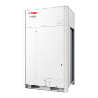
Toshiba MMY-MUP1001HT8P User Manual

Toshiba MMY-MUP1001HT8P
309 pages
To Next Page IconTo Next Page
Page #1 background imageLoading...
Page #1 background image
AIR CONDITIONER (MULTI TYPE)
SERVICE MANUAL
< Super Modular Multi System-u SMMS-u >
Outdoor
MMY-MUP0801HT7(J)P
MMY-MUP1001HT7(J)P
MMY-MUP1201HT7(J)P
MMY-MUP1401HT7(J)P
MMY-MUP14A1HT7(J)P
MMY-MUP1601HT7(J)P
MMY-MUP1801HT7(J)P
MMY-MUP2001HT7(J)P
MMY-MUP2201HT7(J)P
MMY-MUP2401HT7(J)P
MMY-MUP0801HT8(J)P
MMY-MUP1001HT8(J)P
MMY-MUP1201HT8(J)P
MMY-MUP1401HT8(J)P
MMY-MUP14A1HT8(J)P
MMY-MUP1601HT8(J)P
MMY-MUP1801HT8(J)P
MMY-MUP2001HT8(J)P
MMY-MUP2201HT8(J)P
MMY-MUP2401HT8(J)P
MMY-MUP0801HT8P-A
MMY-MUP1001HT8P-A
MMY-MUP1201HT8P-A
MMY-MUP1401HT8P-A
MMY-MUP14A1HT8P-A
MMY-MUP1601HT8P-A
MMY-MUP1801HT8P-A
MMY-MUP2001HT8P-A
MMY-MUP2201HT8P-A
MMY-MUP2401HT8P-A
FILE NO. SVM-21032

Table of Contents

Question and Answer IconNeed help?

Do you have a question about the Toshiba MMY-MUP1001HT8P and is the answer not in the manual?

Toshiba MMY-MUP1001HT8P Specifications

General IconGeneral
BrandToshiba
ModelMMY-MUP1001HT8P
CategoryAir Conditioner
LanguageEnglish

Summary

SAFETY CAUTION

Definition of Qualified Installer or Qualified Service Person

Defines the qualifications and knowledge required for installation and service personnel.

REFRIGERANT (R410A)

Safety Caution Concerned to refrigerant (R410A)

Highlights safety precautions related to R410A refrigerant pressure and handling.

Cautions on Installation/Service

Provides essential cautions for installation and service procedures involving R410A.

4. COMBINED REFRIGERANT PIPING SYSTEM SCHEMATIC DIAGRAMS

4-1. Refrigerant Flow (Cooling)

Illustrates the refrigerant flow path during cooling operation.

4-3. Refrigerant Flow (Heating)

Shows the refrigerant flow path during heating operation.

4-5-1. (1) Refrigerant Flow (Automatic emergency cooling)

Details the refrigerant flow during automatic emergency cooling mode.

5. CONTROL OUTLINE

5-1. Outdoor Unit

Explains the operational control logic for outdoor units, including PMV and fan control.

6. APPLIED CONTROL AND FUNCTIONS

6-3. Method to Set Indoor Unit Function DN Code

Provides instructions for setting indoor unit function codes.

6-4. Method to set Outdoor Unit Function Code No. (O.DN )

Explains how to set outdoor unit function codes.

6-6-3-1. Power peak-cut Control (Standard)

Details the standard power peak-cut control settings and operation.

7. TEST OPERATION

7-1. Procedure and Summary of Test Operation

Outlines the steps for performing a test operation and troubleshooting.

7-4. Address Setup

Covers the procedure for setting addresses for indoor and outdoor units.

7-5. Troubleshooting in Test Operation

Provides troubleshooting guidance for issues encountered during test operation.

7-7-10. Refrigerant leakage detection

Details the procedure for detecting refrigerant leaks.

8. TROUBLESHOOTING

8-2. Troubleshooting method

Outlines methods for troubleshooting based on detected check codes.

9. BACKUP OPERATION (EMERGENCY OPERATION)

10. OUTDOOR UNIT REFRIGERANT RECOVERY METHOD

10-1. Refrigerant Recovery from Troubled Outdoor Unit (Reclaim)

Explains the method for recovering refrigerant from a troubled outdoor unit.

11. REPLACING COMPRESSORS

11-1. Compressor Replacement Procedure (Outline)

Provides an overview of the compressor replacement procedure.

13. P.C. BOARD REPLACEMENT PROCEDURES

Related product manuals