Do you have a question about the Toshiba MR-3021 and is the answer not in the manual?
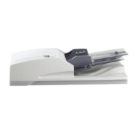
Identifies and lists the primary components of the RADF unit.
Illustrates the internal layout and key parts of the RADF through sectional views.
Shows the physical placement of electrical components and connectors within the RADF.
Explains the meaning and function of symbols for motors, sensors, solenoids, and PC boards.
Presents a block diagram illustrating signal flow between the CPU, drivers, and RADF components.
Details the communication signals exchanged between the RADF and the main equipment.
Explains the operation of the drive system, including feed, read, and exit/reverse motors.
Describes how the RADF detects original size using width and length detection sensors.
Visualizes the RADF's operational logic and sequence of events through a flowchart.
Details the electrical circuits for motors, solenoids, and other functional components.
Step-by-step instructions for removing and replacing the RADF's front, rear, and jam access covers.
Procedures for disassembling and assembling key rollers such as pickup, feed, and separation rollers.
Guides on how to remove and replace the RADF's motors and their associated drive sections.
Details on removing and installing the original pickup and gate solenoids.
Instructions for disassembling and reassembling various sensors and switches within the RADF.
Steps for safely removing and reinstalling the RADF control PC board.
Procedure for removing and installing the hinge stopper mechanism.
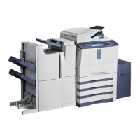
Procedure to ensure correct physical alignment of the RADF with the main unit.
Steps to adjust the RADF's vertical height for proper operation and image quality.
Method for correcting image skew by adjusting the aligning plate and checking copied output.
Procedure to set the correct leading edge position for scanned documents.
Steps to adjust the horizontal alignment of the scanned image.
Procedure for adjusting the copy ratio to match the original document dimensions.
Adjusts the RADF opening/closing sensor bracket for correct detection.
Guides on resolving common mechanical issues like paper jams, skew, and misfeeds.
Steps for diagnosing and fixing electrical faults, connectivity issues, and sensor errors.
Detailed procedures for clearing various types of paper jams within the RADF.
Provides a checklist for routine cleaning, lubrication, and replacement of RADF components.
Instructions for updating the RADF's firmware using a download jig and PC.
Illustrates the component and soldered sides of the RADF control PC board.
Presents the overall circuit diagram showing interconnections of all RADF components.
Detailed circuit schematics for the RADF control PC board for specific models.
| Brand | Toshiba |
|---|---|
| Model | MR-3021 |
| Category | Printer Accessories |
| Language | English |